


RobotGardener Garden Bed Platform DIY Manufacture and Assembly Instructions:
1:Dome 2:Hood 3:Shield 4:Worm Bin Cover 5:Worm Bin 6:Bed 7:Panels 8:Fertigation Tank 9:Control Stand 10:Bed Filling & Amendment 11: Final Assembly
1:Dome
Materials Used: -Steel EMT Conduit, 1”, 10’ (13)
-Bolts, 5/16” x 2” (30)
- Lock Nuts, 5/16” (33)
-Steel Corner Braces, 2 ½” (3)
-Wire, 14-Guage Steel Picture Hanging Wire (>10’)
Tools Used: -Measuring Tape
-Sharpie
-Metal Cutting Tool [Chop Saw]
-Conduit Press [and you have a variety of options, from our DIY choice, to even a hammer.]
-Drill [Drill Press]
-Drill Bit, 3/8”
-Wrench, ½”
-Ratchet, ½”
-Grinders [Belt Grinder] (Optional, Recommended) [Grinder w\ Cut-Off Wheel]
-Pliers w\Wire Cutter
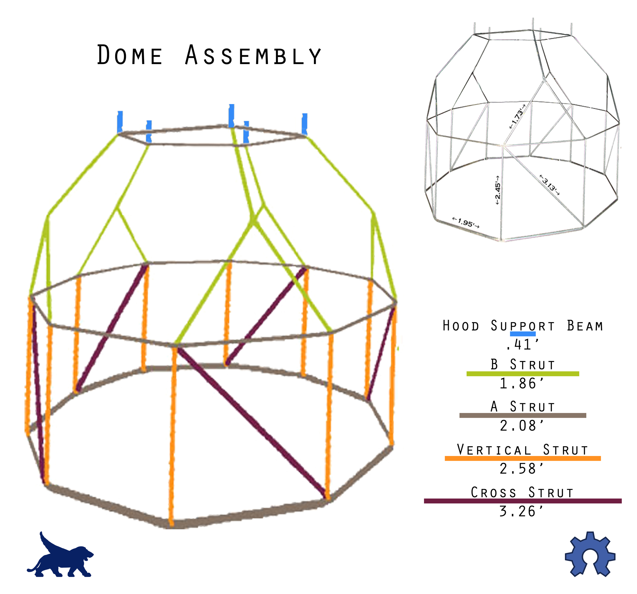
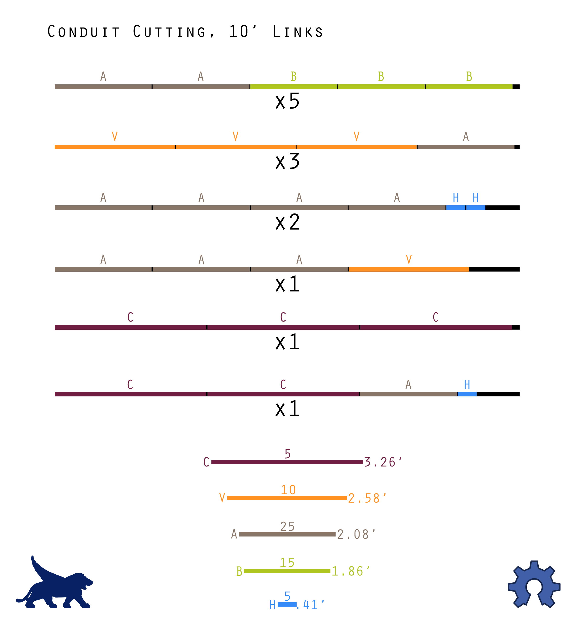
1 Wearing the appropriate safety attire cut conduit links into struts: 25 x A Struts, 2.08’; 15 x B Struts, 1.86’; 10 x Vertical Struts, 2.45’; 5 x Vertical Cross Struts, 3.13’; and 5 x Hood Support Beams, .41’.
2 Flatten both ends of each strut ¾” from the end, level with one another, using a Conduit Press [or hammer, etc.]. Only flatten one end of the Hood Support Beams. There will be less chance of the conduit breaking when it is bent if the ends are crimped in a curved [crescent] shape.
Source: DesertDomes.com 3 Use the Belt Grinder to grind any sharp edges off the ends of the flattened conduit. 4 Wearing the appropriate safety attire: Drill a 3/8” hole in the flattened end of each piece of conduit. The hole should be centered, ¾” from each end. 5 Use the Conduit Press (or a Table Vise, etc.) to bend the flattened ends of the A Struts, B Struts, Cross Struts, and Hood Support Beams (and Not the Vertical Struts) approximately 18 degrees in the same direction. 6 Follow the Dome Assembly Diagram to assemble the dome from the top – down. The 2” bolts go through the intersecting conduit, directed toward the inside of the dome. The lock nuts should be located on the inside of the dome. Hood Support Beams should sit on the outside of the intersection, next to the bolt head. A Struts along the base of the dome should also sit on the outside of the intersection, next to the bolt head, with Vertical and Cross Struts sitting in the inside of the intersection, next to the lock nut.
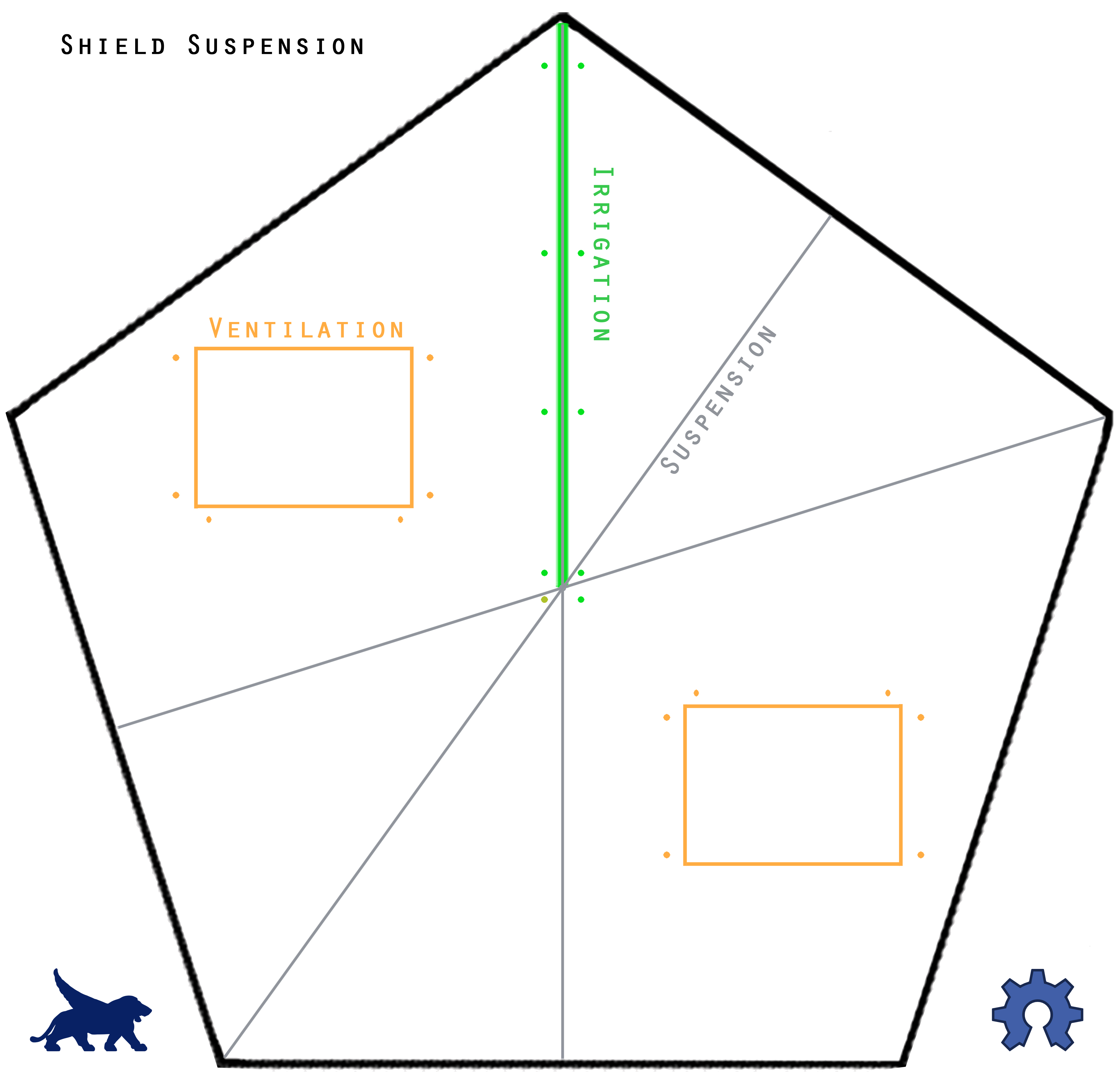
7 Use the wrench and ratchet to tighten all nuts and bolts securely. 8 Wearing the appropriate safety attire: Secure the 3 Steel Corner Braces in a table vice [or alternative] before using the grinder with a cut-off wheel to halve them along their 90 degree bend. Use the belt grinder to grind any sharp edges off the ends of the braces. We are going to use three of these halves later in this section, while the other three halves will be used in the following [Hood] section. 9 If the holes in the Corner Braces are smaller than 3/8”, use the drill press and 3/8” bit to widen one of the two holes in three of the brace halves. 10 Use the Shield Suspension Diagram to determine where the three brace halves will attach in the corners of the crown of the dome. Slide one brace half over the protruding bolt end of each corresponding intersection, with the brace half oriented upward. Use a second lock nut to hold it in place (the brace half now sandwiched between two lock nuts). The brace half should not be sticking above the A Strut ring of conduit. If it is, bend it down and into the bed gradually until it is level with the top of the A Struts. Run the three appropriate suspension wires between the brace halves and the center of the opposing strut, using the Shield Suspension Diagram for reference.
2:Hood Materials Used: -Galvanized Flat Sheet, 2’ x 3’ (3)
-Rivets, 1/8" Short, 1/8" Grip Range Steel Rivet (~40-50)
-Sealant, 10.1 Oz. Aluminum Gray Latex Window and Door Caulk
-Aluminum Angle, 1/8” x ¾” x 10’
-Corner Braces, 2 ½” Steel Corner Braces (5) + 3 Previously Halved Brace Tabs from Dome Section
-Nuts and Bolts, 1" Zinc Plated Round-Head Machine Bolt [VP-Round Combo Machine Screws 10-24 x 1 with matching Nut] (20)
- Flat Washer, #10 x 1/2-in Zinc Plated Standard [SAE] (20)
-Wire, 14-Guage Steel Picture Hanging Wire (<2’)
-Hitch Pin, ¼” x 3" Zinc-Plated Cotterless (3)
Tools Used: -Sharpie
-T-Square, 4’
-Scissors, Heavy Duty
-Clamps
-Steel Plates, x 18” x 2’ (2-3)
-Hand Drill
-Drill Press
-Drill Bit, 1/8”
-Drill Bit, ¼”
-Drill Bit, 3/8”
-Rivet Tool [1/8” Compatible]
-Caulk Gun
-Metal Saw [Chop Saw]
-Screw-Driver [Philips]
-Wrench [Small adjustable]
-Pliers [w\ Wire Cutters]
-Scrapper with Razor
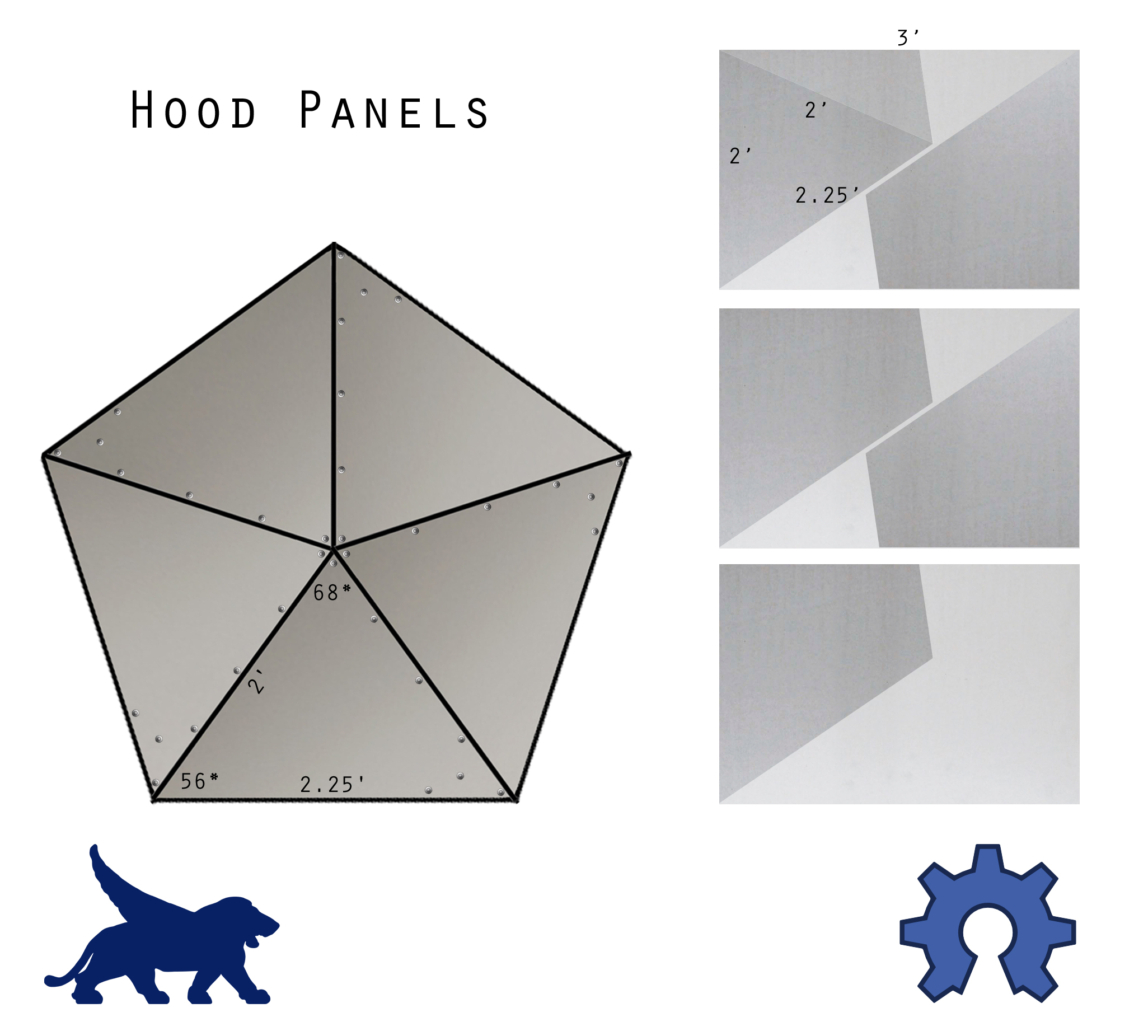
1 Using the Hood Panel Image, mark, then cut five 2’ x 2’ x 2’3” panels from the three sheets of galvanized flat sheet (using the scissors), making sure to leave their complimentary tabs attached.
2 Using a few of the 18” x 2’ steel plates that will be used in the Bed section, make a gentle bend along the 2’ line between the outer-panel triangle, and its interweaving tab. Clamp the plates in-line on both sides of the prescribed line, and use your hands to gently bend the sheet (less than 20 degrees). Make sure to bend all five in the same direction. 3 Interweave the panels together, with the small tab oriented underneath, and rivet them together, making the hood. Use the hand drill and 1/8” bit (or metal punch and hammer) to make your rivet holes. Five rivets along the crest of the outer panel, and 2-3 in tab along the bottom should be enough. Make sure to rivet outside-in, pushing the rivets through from the top of the hood. Cut a small pentagon shape, with edges approximately 3” in length, from the flat sheet scrap. Rivet the piece into the peak of the inside of the hood. 4 Cut the aluminum L-beam into five equal lengths, approximately 2’ each. These pieces should also have their ends each cut at a complimentary 45 degree angle. One side of the ‘L’ should have both of its ends sloped 45 degrees, while the other side of the ‘L’ maintains its flat edge. 5 Place a corner brace near the flat ends of each piece of L-beam and mark the holes to be drilled. 6 Use the drill press to drill the four ¼” holes in each piece of aluminum L-beam. 7 Attach the corner braces to the aluminum L-beam with the sloped edges of the beam next to one another. The screw top should be on the outside of the frame, against the brace. Once a corner’s corresponding four nuts have been tightened securely, gently bend the brace open a few degrees, gradually shaping a pentagon. All of the L-beam edges should be oriented the same way, creating an inner lip in the frame. Use the Hood Latch Tab Image to determine the proper placement of the three previously halved corner braces. These tabs mount outermost in their intersections, sitting against the machine screw’s head.
8 Wire the aluminum frame into the hood. The frame should be oriented with the sloped edges\lip sitting closest to the peak, creating an aluminum rim for the hood support beams to sit in the corners of. Use the drill to make holes in the hood, near the corner, on the interweaving panel side (going through two sheets), above and below the hood frame. Run a piece of wire through the holes and twist it securely around the aluminum frame, with the twisted ends of the wire up and inside the hood. 9 Waterproof the hood by sealing it with the caulk. Squeeze the appropriate amount of caulk between the interweaving panels, as well as into the space in the peak of the dome, underneath the small pentagonal piece. After the caulk dries slice and\or scrape any excess off with a razor. 10 Place the hood onto the dome’s hood support beams, bending the hood support beams as necessary to sit properly in the corners of the hood’s frame. Mark the entry and exit locations for the hitch pins on the three hood support beams corresponding to the hood’s three hitch tabs. Tip the dome on its side if necessary, and drill the 3/8” holes completely through the three hood support beams. Once the dome is upright, the hood can be placed on top and the three hitch pins slid into place, securing the hood to the dome.
3:Shield Materials Used: -Clear Acrylic Sheet [Plexiglas], 3’ x 4’ ( 3’ x 6’ is what we’ve been having to buy)
-Wire (<5’)
-Fans, 4-Sone 50 CFM Bath Fan (2)
-Full Pattern Plastic Shrub Head Sprinkler with Nozzle, 1/2"
-Plastic Swing Joint Elbow 1/2" MPT x 1/2" FPT
- ½” MPT - ¾” FHT PVC Swivel
-Garden Hose
-Male Hose Repair End
-Female Hose Repair End
-Hose Washer
Tools Used: -Sharpie
-T-Square, 4’
-Rotary Tool [Dremel]
-Dremel Carving Bit
-Pliers [w\ Wire Cutters]
-Scissors
-Screwdriver
1 Use the Shield Cutting Image as a guide when drawing the pentagonal shield onto the acrylic sheet. Take one of the ventilation fans and measure its width. Then measure a diagonal line along the fans side, running from the front of the fan, just above the fan’s vent, to the bottom of the van, around an inch from the rear. This should be the plane of the shield once the fan is mounted in place, with its vent pointed down into the dome. These measurements will be those used in marking the two ventilation ports on the acrylic sheet now. Mark the locations for wire retention accordingly for both ventilation and irrigation.
2 Wearing appropriate safety gear, and making sure to use a well-ventilated space: Use the rotary tool with a small carving bit to remove unwanted Acrylic Sheeting. This method takes time, as you’re basically melting through the Acrylic with the spinning bit. 3 When the Shield is ready for installation, remove the clear plastic protective covering, and place the shield on top of the dome’s suspension wires, using the Shield Suspension Diagram if necessary to properly orient fan ports and irrigation hose path.
Place the ventilation fans into their ports, facing down and inward, and wire them in place. Next assemble the irrigation. First connect the ½” full pattern shrub sprinkler head, with a nozzle, to the ½” MNPT – ½” FNPT elbow. Next, connect the ½” MPT – ¾” FHT PVC Swivel. You can now connect you connect your irrigation hose. Your hose should be made to length, using the garden hose repair ends, varying based on its distance from the control stand. When the irrigation is assembled, wire it into place, with the sprinkler head oriented in the center of the shield, oriented downward over the bed. The hose leading to the control stand should also be secured to its relative B Strut on the dome, adding support.
4:Worm Bin Cover Materials Used: -Wood Panel, 3/4” x 24” x 36”
-Handle, 4”-3/4" Zinc Screen Door Pull
-Drip Line 3/4" Faucet Adapter with 1/4" Barb Outlet,
-Drip Line, ¼”, <4’
-Drip Line Stopper
-Zip Ties (~12)
- Wood Screws, ~1”-1 ½” (4)
-Poster board, 2.5’ Square
Tools Used: -Pencil
-String (~2’)
-T-Square, 4’
-Sharpie
-Circular Saw
-Sandpaper [Block]
-Screwdriver\Drill
-Drill Bit, ¼”
1 Draw the decagonal template that will be used for manufacturing both the worm bin lid and the worm bin onto the poster board. Mount the screw into the center of the poster board. Using a 12.64” length of string connected to the screw mark the circumference with a pencil. Next mark the ten even 7.81” edges, their joints sitting along the circumference. You can use the 7.81” steel plates from the Worm Bin section as a guide. Once the template is completed, cut off the unnecessary poster board around the decagon. Lay the template on top of the wood panel, and mark the wood to be cut. Set the template aside to be used in the Worm Bin section. Mark two small rectangles in the scrap area designated for removal. These rectangular blocks should measure 1” x 7.5”. 2 Use a circular saw to cut off the excess wood. Also cut out the 1” x 7.5” wood blocks. 3 Clean up the edges of wood with the sandpaper on a block. 4 With the Worm Bin Lid Image as a guide, use the string compass to mark a circle with a 6” radius in the center of the decagonal panel. Mark a line from a corner of the decagon to the circle. Since this will be the path of our mounted dripline, which we don’t want to crimp, free-sketch a gradual bend leading from the line into the circle. Mark paired holes on either side of the path to be drilled, using the Worm Bin Lid Image as a guide.
5 Mount the rectangular blocks in their appropriate locations using the wood screws. Mount the handle on the top of the panel, opposite the wood blocks, centered. 6 Drill the ¼” drip line retention holes. Use zipties to mount the drip line in place. The drip spouts should be oriented away from the panel, and the ziptie connection should be kept on the underside of the lid. Do not over tighten the ziptie, restricting flow. When the drip line is mounted clip off the excess ziptie. Place a dripline plug in one end of the dripline, and the ¾” MHT adapter in end at the edge of the panel. 5:Worm Bin Materials Used: -Steel Plate, 12-Guage, 24” x 25 3/16”
-Steel Plate, 12-Guage, 6” x 7 13/16” (10)
-Steel Plate, 12-Guage, 6” x 6” (8)
-Steel Plate, 12-Guage, 12” x 9” x 9” (4)
-3/4" x 1/2" Female Garden Hose to FIP Adapter, Brass
-1/2" Barb x 1/2" MIP Hose Adapter, Brass
-Washers, >1/2” <5/8” Inner-Diameter (2)
-5-Gallon [Paint] Spreader Screen, 10” x 11”
-Bright Aluminum Screen, 14 ¼” Square
Tools Used: -T-Square, 4’
-Sharpie
-Drill [Drill Press]
-Hole Saw, ¾”
-Drill Bit, Anular, 1”
-Grinder [Cut-Off Wheel]
-Grinder Polishing Wheel
-Welder
-Clamps
-Table Vice
-
Rotary Tool [Dremel]
-
Dremel Grinding Bit
-
Metal Shear
1 Use the decagon template created in the Worm Bin Lid section to mark the 24” x 25 3/16” steel plate for cutting. Mark an 11” square in the center of the steel decagon. Mark a 2” square in one of the peripheral spaces slated for scrap. Mark the 9” x 9” x 12” triangular steel plates with a level 2” line between the 9” sides, designating the peak of the triangle to be removed. 2 Wearing the appropriate safety attire: Use the grinder with the cut-off wheel to remove the predetermined excess steel: the edges of the steel decagon; the 10” square from its center; the 2” square from its scrap piece; and the peaks of the triangles, leaving a cap-less 2” edge. Use the grinder with the polishing wheel to clean the rough edges. 3 Wearing the appropriate safety attire: Mark and drill the eight (or four pairs of) 7.81” x 6” steel plates with the appropriate 1” hole, using the Earthworm Porthole Image as a guide.
3 Wearing the appropriate safety attire: Weld the four modified triangular plates into a capless pyramid with a 12” square base. Weld the 2” square onto the pyramid’s cap. Weld the worm bin porthole plates in the appropriate corresponding order to the steel decagon. Weld the steel pyramidal drain to the underside of the worm bin’s square drain port. Weld the eight 6” x 6” steel plates to the base of the bin, paired on each side of the pyramid, making a stand. Use the hand drill to drill a ¾” hole in the center of the 2” square at the cap of the pyramidal drain. 4 Trim the small legs and extra length off of the paint spreader screen, aiming for a sturdy 10” square. You can use what tools are available, such as the grinder with the cut-off wheel, or an alternative. Take an approximate 14.25” square of aluminum screening and fold it around the 10” square spreader screen, the points of the aluminum screen meeting in the center of the back side. Crease the aluminum screen firmly along its fold lines, helping it stay in place. 5 Clamp the ½” end of the ¾” FHT x ½” FPT brass fixture in a table vice. Carefully remove the ¾” end of the fixture with the grinder, using the cut-off wheel first, followed by the polishing wheel, working your way down slowly. If the inner diameter of your fender washers is too small to fit over the ½” MPT, use the rotary tool with a grinding bit to increase the inner diameter. Mount the ½” brass barb in the underside of the worm bin drain with a fender washer, and secure it on the inside of the drain with another fender washer and your modified ½” FPT brass fixture. Place the square screen, folded aluminum edges down, into the square drain cavity.
6:Bed Materials Used: -Slotted Angle Metal, Plated, 18-Gauge , 1 ¼” x 1 ¼” x 8' (2)
-Steel Plates, 16-Guage, 18” x 2’ (10)
-Bolts, 5/16” x ½” (40),
- Bolts, 1” x 5/16” (20)
-Bolts, 1 ½” x 5/16” (20)
-
Nuts, Acorn, 5/16” (40)
-
Nuts, 5/16” (20)
-Lock Nuts, 5/16” (20)
-Fender Washers, 5/16” x 1 ½” (30)
-3/4"FHT x 1/2" FIP, Brass (2)
-3/4" MHT x 1/2" MIP, Brass (2)
-1/2" Barb x 1/2" FIP, Brass
-1/2" Barb x 1/2" MIP, Brass
-Washers, >1/2”<5/8” Inner-Diameter (6)
-Pond Liner, 500 Gallon PVC/Nylon Mesh, 10’ x 13’
-Expanded Shale (8 x 40lb bags)
- PVC Pipe, Schedule-40, 1” x 12’
-PVC End Caps, 1” (2)
-PVC Elbows, 1” (2)
- PVC Tee, 1”
-¾” MHT x 1” Schedule-40 PVC
-Clear Vinyl Tubing, ½” Inner-Diameter, 4’
Tools Used: -Measuring Tape
-T-Square, 4’
-Sharpie
-Metal Saw [Chop Saw]
-Clamps
-Drill [Drill Press]
-Drill Bit, 3/8”
-Drill Bit, ¾”
-Hammer [4lb]
-Wrench, ½”
-Ratchet, ½”
-Rotary Tool [Dremel]
-Dremel Grinding Bit
-Hand Drill
-Drill Bit, ¼”
-PVC Pipe Cutter
-Scissors
-Knife
-Aquarium Grade Silicon
-PVC Glue and Primer
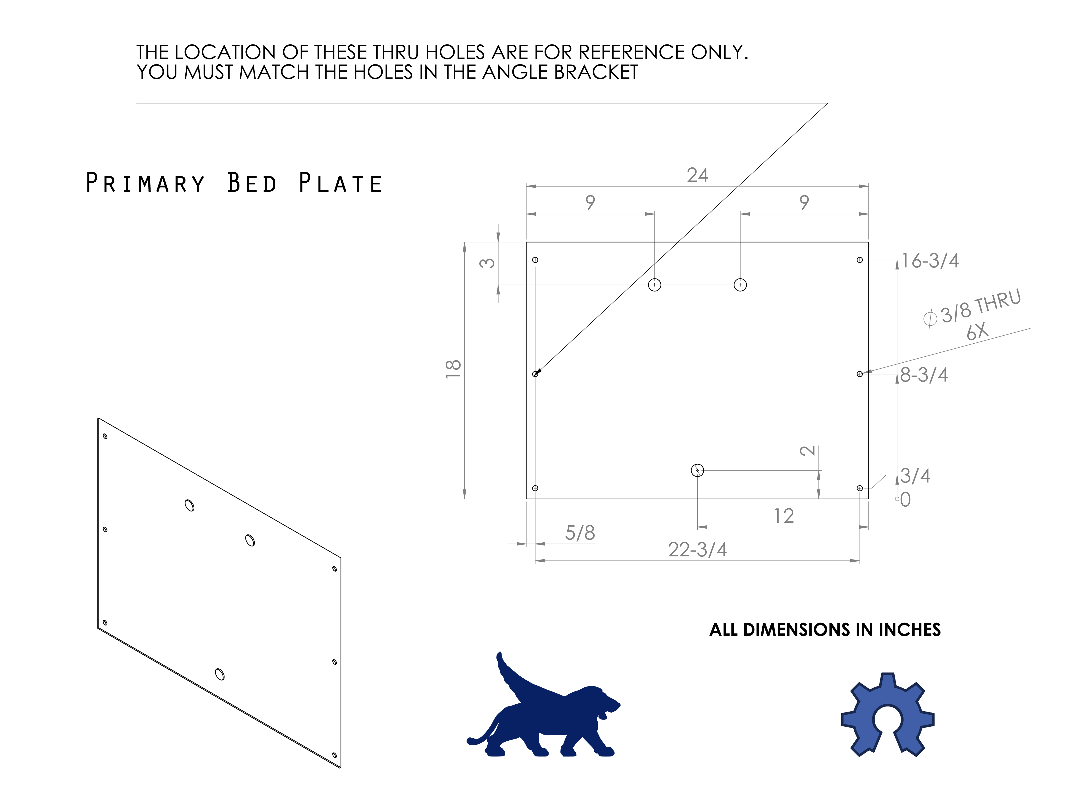
1 Cut the sections of slotted angle metal that will join the bed plates. When cutting slotted angle metal it is preferable to cut centered between slots, for uniformity. Place the slotted angle metal against the 18” side of a steel bed plate and determine how many slots will fit along this edge. Wearing the appropriate safety attire: Cut ten even lengths of slotted angle metal just shorter than 18” in length. 2 Place one length of slotted angle metal against the 18” edge of a steel bed plate and mark the three bolt holes to be drilled on each side, using the Primary Bed Plate Image as a guide. Mark the three 7/8” holes to be drilled in the primary bed plate, using the Primary Bed Plate Image as a guide.
4 Wearing the appropriate safety attire: Drill the six 3/8” holes in the bed plates. For uniformity, the plates may be clamped together, drilling the holes through all ten plates at once. Drill the three 7/8” holes in the primary bed plate. 5 If your fender washers won’t fit over ¾” MHT, use a rotary tool with a grinding bit to increase the inner diameter to fit. You need six fender washers with a clear inner diameter. Mount the brass fixtures in the primary bed plate, using a fender washer on each side of the plate for reinforcement. Center port that will be oriented at the top (opposite of the orientation in the image), provides a ¾” FHT on the front of the plate and a ¾” MHT on the back of the plate. The bottom left port provides a ½” brass barb on both the front and back of the plate. The bottom right port provides a ¾” MHT on the front of the plate and a ¾” FHT on the rear. Don’t over-tighten the fixtures, as they will be removed and reinstalled during bed installation. 6 Hammer the sections of slotted angle metal from 90 degrees, as close to 144 degrees as possible. Determine and clear the installation space: Determine an installation location capable of providing electricity, water, and either Ethernet or Wi-Fi. Determine the future location of the control stand. The primary bed plate will sit collocated to the control stand. Consider lighting. Is there adequate sunlight, or are you installing the appropriate spectrum of lights? For best drainage when installing on an unleveled surface, locate the primary bed plate at the lowest elevation. Further locate the control stand at a lower elevation than the primary bed plate. 7 Lay out the bed plates in formation, with the primary bed plate in its appropriate location. No brass fittings should be in the plate at this time. Lay the 10 sections of slotted angle metal between the plates. Using forty ½” bolts and forty acorn nuts, assemble the bed. The slotted angle metal sits on the outside of the plates, against the bolt head. The acorn nut sits on the inside of the bed, seated against the steel plate. Leave the top two holes in each plate vacant, only using the bottom for holes at this time. Tighten securely with wrench and ratchet. Install twenty 1 ½” bolts in top holes, with a regular nut. Place the dome on top of the 1 ½” bolts, with the irrigation directed toward the primary bed plate. Adjust bed wall placement to suit dome. Remove the dome without disturbing bed wall placement, and remove the twenty 1 ½” bolts from the top of the bed wall, leaving them empty. 8 Put a layer of fill dirt or sand into the bed before laying pond liner in centered. Gently push the liner down to the base of every plate, keeping a relatively even amount of excess hanging over the edges. Fold the Liner when necessary to avoid bunching. Pour a few bags of expanded shale into the lined bed, 2”-3”. Install the brass fittings back into the primary bed wall. While making sure to keep the pond liner properly situated, use a knife to cut a small circular hole in the pond liner directly over the primary bed wall port, large enough to barely force the threaded end of the brass fixture through with some force. Apply a fairly generous amount of the aquarium silicon to the inside of the washer that will be seated against the pond liner, and install the brass fittings in their appropriate locations, tightening securely. 9 Cut the 1” PVC pipe into five length: two 3’ lengths, one 2’3” length, one 1’9” length, and one 1’6” length. Drill a series of ¼” holes in a straight line along the tops of the pipe, leaving the last couple inches of pipe undrilled. Rinse, and remove PVC shavings. Place 1” end caps on one end of the 3’ lengths. Place a 1” elbow at the opposite end of the 3’ lengths. Place the 2’3” length in the open end of one of those elbows, and the 1’9” length in the other. Connect the 2’3” and 1’9” lengths, in-line, using the strait of the 1” tee. Connect the 1’6” length to the remaining opening at the bottom of the 1” tee. The drain should resemble an off-center goal post. The bed drain will connect to the bottom right port of the primary bed plate. With that in mind glue the pieces together with holes oriented down. After drying, rinse well. Place the drain in the bed, drain holes down. Thread the ¾” MHT to 1’ PVC adapter tightly into the ¾” FHT brass fixture in the bottom right of the primary bed plate, and glue the 1” PVC drain to the adapter. Attach the ½” clear vinyl tubing to the brass barb on the inside of the primary bed plate, located on the bottom left side, and run enough length reach the center of the bed and up a few inches to connect to the worm bin drain. 10 Add the other bags of expanded shale, just covering the bed drain, and the vinyl tubing. Connect the clear vinyl tubing to the ½” brass barb at the base of the worm drain, allowing the tubing to sit between stand plates as the worm bin is placed in the center of the bed, on top of the expanded shale. The corners of the worm bin are pointed at the centers of the bed walls. Fill the bed with soil and compost. Reference Bed Filling section. 11 With the bed properly filled, install twenty 1” bolts in the bed’s twenty top holes. Pull the liner into place over the top of the bed. Make a small hole on either side of the liner and force the bolt through. A 5/16” fender washer can fit onto one of the two entering bolts on the inside of the bed. Tighten twenty lock nuts securely with the wrench and ratchet. Trim off the excess pond liner, leaving a few inches of overhang evenly around the edge.
7:Panels Materials Used: - Hook and Loop Adhesive-Backed Reclosable Fastener [Velcro, 3M SJA-7501 & 7502], 1” Wide x 50 Yards (1 Roll Each)
- Plastic Sheeting, Clear, 6 Mil, 10' x 25'
-Sun Screen Fabric, Green, 6' x 40'
Tools Used: -T-Square, 4’
-Sharpie
-Scissors
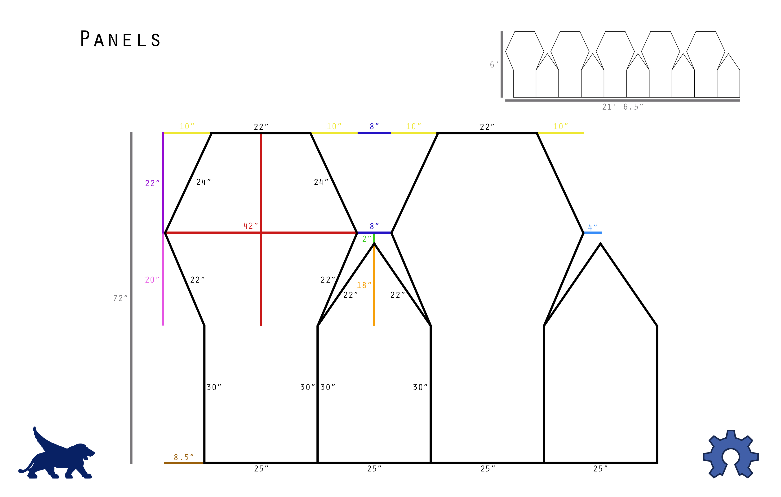
1 Using the Panels Image as a guide, draw the ten cover panels onto the material.
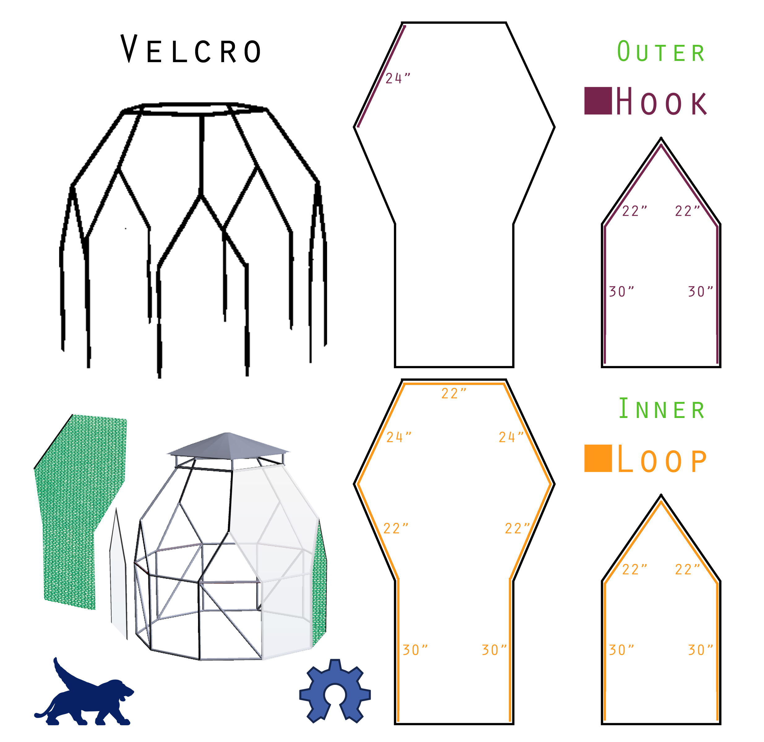
2 After all ten of the panels have been drawn on the material (five with hexagonal tops and five with triangular tops), cut the panels out with scissors. Cut away from the material, not into it, as you don’t want any small slits that could lead to tears later. 3 Using the Panel Velcro Image, place the appropriate length of either hook or loop Velcro on each panel in appropriate locations. Use scissors to cut the length, then remove the adhesive protection before pressing firmly in place along the edge of the panel. The Velcro should sit right along the panel edge, not hanging over the material, and not letting the material have an overhang.
Lay hook Velcro along the crests of the corresponding struts on the dome: along the tops of the A Struts at the top of the dome, just under the plexiglass; on the outer crests of all the B struts; and along all the crests of the Vertical Struts. Press the adhesive firmly to the steel conduit to affix. Now Velcro the panels to the dome. The triangular panels go on first. The hexagonal panels go on second, with their top edges velcroing just under the plexiglass shield (its weight holding the panels secure), and the upper left edge weaving under the hexagonal panel adjacent. Press all the Velcro firmly together once it is in place.
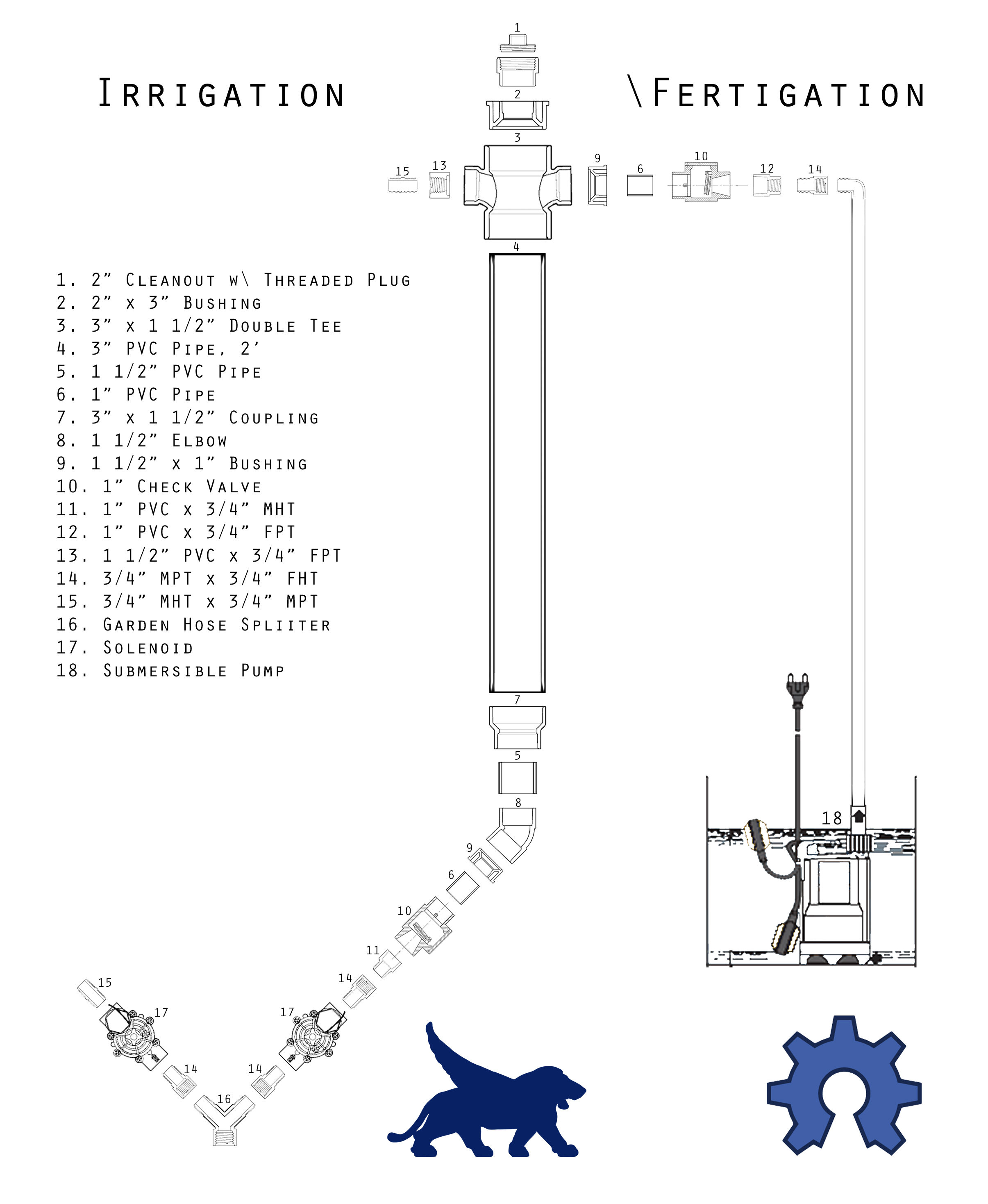
8:Fertigation Tank Materials Used: -2” Threaded PVC Cleanout w/ Plug
-3” x 2” PVC Bushing
-3” x 3” x 1 ½” x 1 ½” PVC Double Tee
-3” PVC Pipe, 2’
-1 ½” PVC Pipe, ~2”
-1” PVC Pipe, ~1’
-3” x 1 ½” PVC Coupling
1 ½” PVC Elbow
1 ½” x 1” PVC Bushing (2)
-1” Inline PVC Check Valve (2)
-¾” MHT x 1” PVC Adapter
-¾” FPT x 1” PVC Bushing
-¾” FPT x 1 ½” PVC Bushing
-¾” MPT x ¾” FHT Swivel
-¾” MHT x ¾” MPT
Tools Used: -PVC Primer and Glue
-PVC Pipe Cutter
1 Assemble the fertigation tank in three sections. The initial irrigation check valve system is first. Glue the ¾” MHT x 1” PVC adapter into the inlet end of a 1” inline check valve. 2 The lower mixing vessel is next. Glue the 2’ of 3” PVC pipe into the 3” x 1 ½” coupling. Glue the ~2” of 1 ½” PVC pipe into the end of the coupling, before gluing the other end into the 1 ½” elbow. A 1 ½” x 1” bushing is then glued into the open end of the elbow. 3 Last is the upper mixing vessel. Glue the 2” threaded cleanout with plug into the 2” x 3” bushing. Glue that 3” bushing into the top of the double tee. Thread the ¾” MPT x ¾” MHT into the ¾” FPT x 1 ½” bushing, and glue the bushing into one side of the double tee. Glue the ¾” FPT x 1” bushing into the inlet of the second 1” inline check. Use the pipe cutter to cut a ~2” length of 1” PVC pipe, and glue it into the outlet end of the 1” inline check. Glue the remaining 1 ½” x 1” bushing into the other side of the double tee, before gluing the 1’ section of PVC pipe protruding from the inline check into the bushing. The fertigation tank will be left in sections until its alignment is properly marked in future sections.
9:Control Stand Materials Used: -Galvanized Flat Sheet, 2’ x 3’ (4)
-Steel Corner Braces, 1 ½” (8)
-Galvanized Roofing Nails, ¾”
-Fender Washers, 5/16” x 1 ½” (16)
-Steel EMT Conduit, ¾”, 10’
- Channel, Half Slot, 14-Guage, 10’
-Universal Pipe Clamp, ¾” (8)
-Door Hinge, 3”, with 1/2” Screws (2)
- Plywood, ½”, 4’ x 8’
-Bolts, 5/16” x 2” (10)
- Bolts, 5/16” x 4” (2)
U-Bolt [Square], 6” x 3/8”
-Lock Nuts, 5/16” (12)
-Lock Nuts, 3/8” (2)
-Wood Screws (~40)
-Irrigation Valve Box, 12” x 17”
-
Junction Box, PVC, 12” x 12”
-
¾” FHT Y-Splitter to 2 x ¾” MHT
-
¾” FHT x ¾” MPT Swivel (3)
-
¾” MHT x ¾” MPT Adapter
-Electric Water Solenoids, ¾”, In-line w\ Flow Control (2)
-Hose Washer (8)
-Wire, 14-Guage Steel Picture Hanging Wire (~2’)
-RobotGardener Electronics Package
Tools Used: -T-Square, 4’
-Sharpie
-Pencil
-Circular Saw
- Metal Cutting Tool [Chop Saw]
-Hammer
-Scissors
-Rotary Tool [Dremel]
-Dremel Cut-Off Wheel
-Wrench, ½”
-Ratchet, ½”
-Screwdriver\Drill
-
Drill Bit, 3/8”,
-
Drill Bit, 7/16”
-Hole-Saw, 1”
-Hole-Saw, 1 ¾”
-Hole-Saw, 2”
1 Wearing the appropriate safety attire: Using the Wood Cabinet Image for reference, cut the plywood into six pieces with the circular saw.
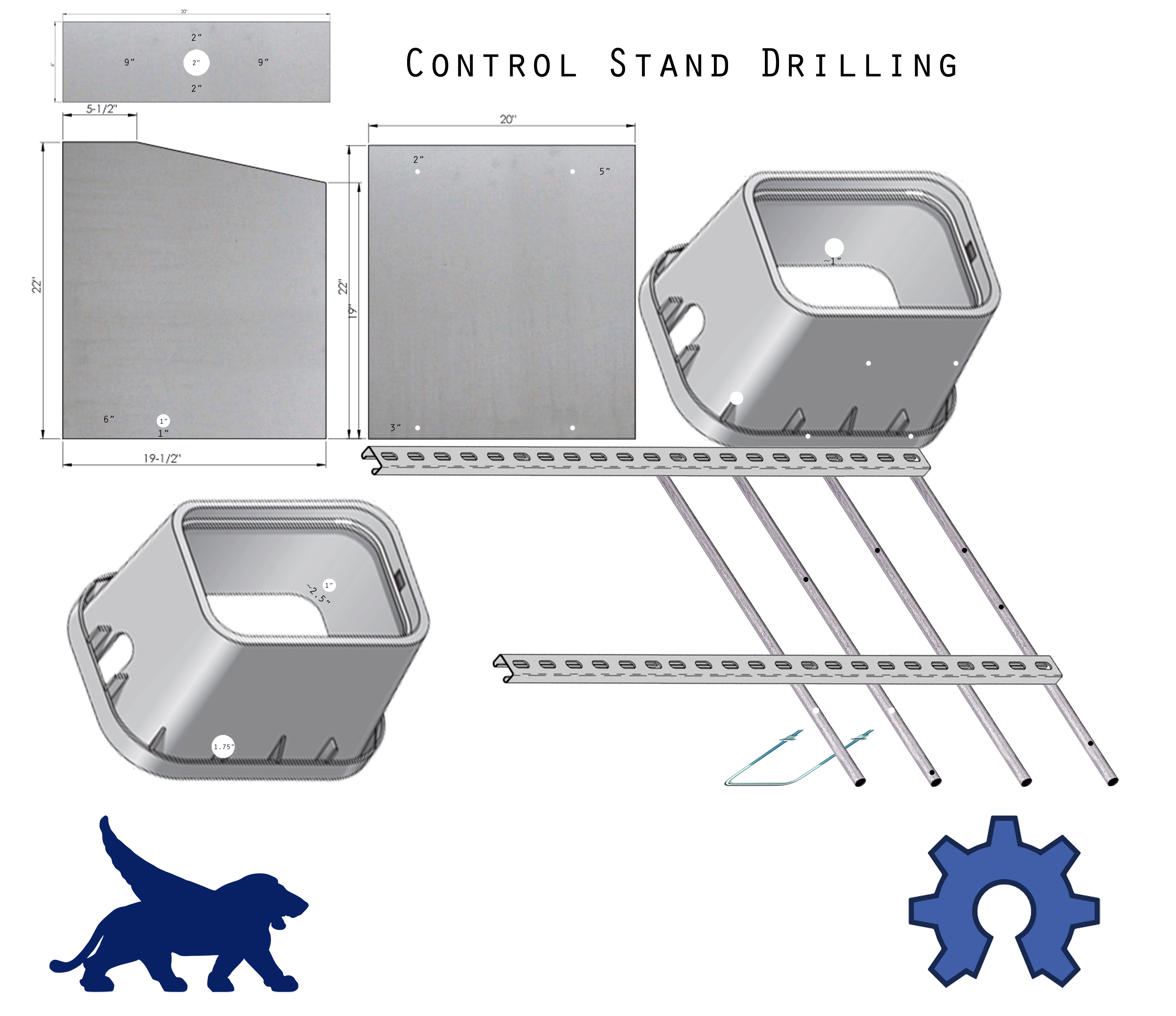
Using a Metal Chop Saw: Cut the 10’ link of ¾” Conduit into 4 even 2 ½’ lengths; Cut two 42” lengths of half-slot channel. For uniformity, make cuts centered between slots. Again, when cutting bracketing, for uniformity it is important to cut lengths on centers between holes. I’m cutting 2 lengths of approximately 42” off the ends of the piece so I get both of the polished ends. 2 Assemble the wood cabinet using the corner braces to frame it. Use the Control Stand Plywood Assembly Video for reference. Place two corner braces between the rear cabinet wall and each of the sides. Place one corner brace between each side wall and the cabinet’s front wall. Place one corner brace between the cabinet’s top and each of the side walls. Once the cabinet is framed place a number of wood screws along the outer face of each corner for reinforcement. Use the Dremel and cut-off wheel to cut off any screw points that might be left protruding after corner brace installation. Using the Control Stand Drilling image as a reference, drill the appropriate 3/8”, 1”, and 2” holes in the wood cabinet.
Drill the appropriate 3/8” holes in the back of the irrigation box. Also drill the appropriate 1” hole along the back left corner of the irrigation box (left side when facing the 3/8” holes drilled). The 1” hole should be centered on the crest of the corner, ~2 ½” up.
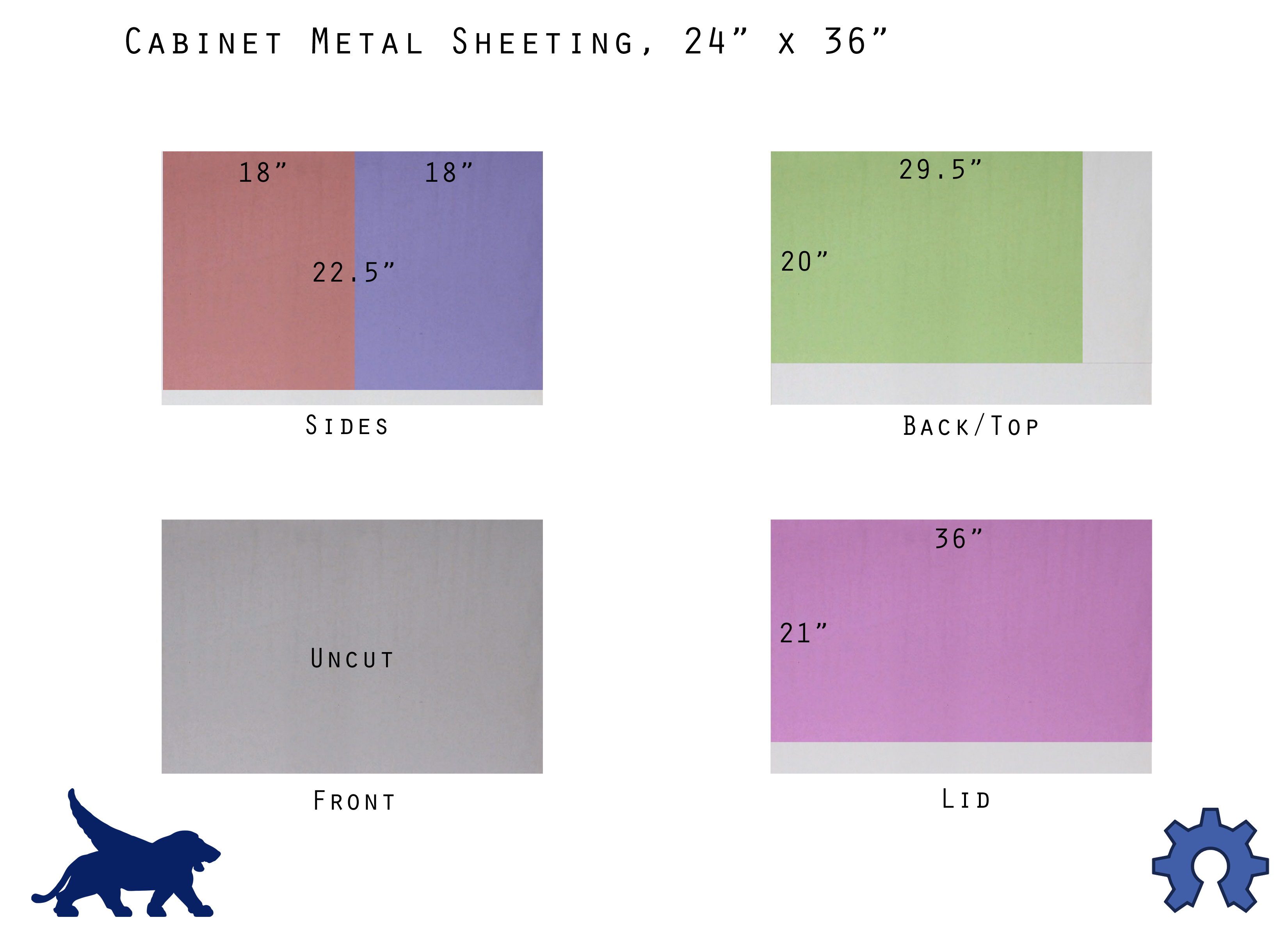
3 Using the Cabinet Metal Sheeting image, mark and cut three of the four sheets.
Cover the wood cabinet with the galvanized sheeting. Tack the bottom edge of the sheet in position on the under edge of the wood cabinet using the hammer and roofing nails, before shaping the sheet over the cabinet’s corners, working toward the cabinet’s opening. Tack any excess sheeting inside the cabinet. Cover the cabinet’s lid in the same fashion. Use the drill and appropriate bits to remove the sheet metal from the pre-drilled 3/8”, 1” and 2” holes. 4 Attach the two lengths of channel to the rear of the cabinet. When facing the rear of the cabinet the channel should be flush with the left side of the cabinet’s rear and extending to the right, with the open face of the channel facing away from the cabinet. Slide fender washers into the channel’s end, before sliding a 5/16” bolt through the washer, channel, the pre-drilled 3/8” holes in the cabinets, and another fender washer on the inside of the cabinet. Secure the bolt snuggly on the inside of the cabinet with a lock nut. Mount the irrigation box on the opposite end of the channel in the same fashion, placing fender washers into the channel before sliding the bolts through the washer, channel, irrigation box holes, and another washer on the inside of the irrigation box. Secure the bolt on the inside of the irrigation box, but not so much as to bend it upward and off the ground. 5 Attach the four pieces of conduit to the channels using the universal pipe clamps. Use the Control Stand Drilling image as an estimation on their placement. Place the fertigation tank mixing vessl in place between the 1st and 2nd conduit beams. This portion of the mixing vessel hasn’t been glued together yet. Use a ~6”-8” piece of 1” PVC pipe extending from the elbow at the bottom of the mixing vessel by placing it into the 1” entry port on the corner of the irrigation box. When the lower mixing vessel is seated comfortably on the channel and into the irrigation box, adjust the unglued tee of the upper mixing vessel to sit inline with channel. Draw a line down this connection on the PVC to mark its placement for future gluing. Twist the length of wire around the mixing vessel and the 1st and 2nd beams to hold it in place temporarily. Connect the irrigation solenoid assembly. Connect two ¾” female hose to ¾” MPT swivels to each male end of the hose splitter, before threading the swivels into the inlet end of the two electric water solenoids. The solenoid that leads left has the outlet end threaded with the ¾” MPT to ¾” MHT adapter, while the solenoid on the right has its outlet end threaded with a ¾” MPT to ¾” female hose swivel. Thread the initial check valve portion of the fertigation tank that was glued in the last chapter to the ¾” female end of the swivel at the outlet end of the right solenoid. Place the irrigation solenoid assembly into the irrigation box. When facing the front of the irrigation box: The female end of the splitter should be sitting under the front of the box; the left solenoid should be exiting open end at the left of the irrigation box; and the initial check valve system should be inline with the temporary piece of 1” PVC leading to the fertigation tank. When the irrigation solenoid assembly has been properly aligned: Mark the position of the female end of the hose splitter on the outside of the irrigation box; Mark the1” PVC pipe leading to the mixing vessel where it should be cut to fit properly into the initial check valve system. After the irrigation box and pipe have been marked, remove the irrigation solenoid assembly. Drill a 1 ¾” hole, centered, 1 ½” above the spot marked for the splitter placement. Remove the fertigation tank. Withdraw the temporary piece of 1” PVC pipe and cut it to the appropriate length. Glue the 1” PVC pipe in the open end of the elbow at the base of the mixing vessel. Glue the 3” tee to the top of the 3” pipe, in the position marked. Once the connections have dried, rinse the mixing vessel very well. Place the empty outdoor box on the top edge of the top piece of channel, with its back against the 3rd conduit beam. The connection tabs of the outdoor box should be extending to the sides, the holes in the tabs sitting centered over the 2nd and 4th conduit beams. Readjust the location of the 4th beam if necessary; the 2nd beam must remain 6” from the 1st beam. Mark the locations of the two holes to be drilled. Place the empty 1’ outdoor box on the back of the control stand: its back against the 3rd conduit beam; the connection tabs of the outdoor box should be extending to the sides, the holes in the tabs sitting centered over the 2nd and 4th conduit beams; just under the universal pipe clamps connected to the top channel. Mark the two holes to be drilled in the conduit for the box connection. Using the Control Stand Drilling image: Mark the 1st and 2nd conduit beams along the rear crest ~7” from the top of the beam (these two locations will have 7/16” holes while all the rest will have 3/8” holes). Mark the 3rd and 4th beams along the rear crest ~8” from the bottom. Mark the irrigation box ~8” from the bottom in line with the 3rd and 4th beams. Drill the six 3/8” holes in columns 2-4, and the two 7/16” holes in columns 1 and 2. Place the fertigation tank back in place on the control stand, with the 1” PVC pipe entering the irrigation box. Secure the vessel in place by sliding the 6” square u-bolt across the tank and through columns 1 and 2, securing it with the 3/8” lock nuts on the front of the conduit. Glue the initial check valve to the 1” PVC pipe on the inside of the irrigation box. After it has had time to dry, connect an incoming hose to the initial check valve, and an outgoing hose to the male thread at the top of the mixing vessel, and rinse the fertigation tank well with water. Place the 4” bolts through the two bottom holes on the 3rd and 4th beam, and slide them into the holes drilled in the side of the irrigation box. Secure the bolts in the inside of the irrigation box with a washer and a lock nut. Do not over tighten. If the empty PVC junction box does not have a 1 ¾” porthole already drilled on its underside, drill that hole centered. Install the empty router box to the back of the control stand, sliding a 5/16” bolt through the connection tabs, then through the conduit on the 2nd and 4th beams, before securing it with a lock nut. Install the RobotGardener Electronics Unit to the front of the control stand, securing the 5/16” bolts on the rear of the 2nd and 4th beams with a lock nut. Taking the 6 ½” wide piece of scrap metal sheeting, cut a 7” x 6” rectangle. Mark the center of the bottom 7” edge. Place the irrigation solenoid assembly into the irrigation box with the primary female swivel exiting the port drilled on the front left of the box. The metal sheet will have a narrow channel cut into it so it can slide over the splitter’s main section, behind it’s swivel, creating a choke to keep it extended. Place the bottom edge of the sheet into the outer rim along the base of the irrigation box and mark the height from the centered base mark to the top of the splitter piece, not its swivel. Also measure the width of the width of the splitter piece, which should be smaller than the swivel, and mark this width centered from the base to the height mark, rounding the top of this channel to sit on the splitter’s neck. Completion of the Control Stand and its installation will be in section 11, Final Assembly.
10:Bed Filling & Amendment Materials Used: -Soil (¾ cubic yard)
-Compost (¾ cubic yard)
-Humate [Optional]
-Zeolite [Optional]
-Dragonite [Optional]
-Cow Manure, Fresh (~3-4 Gallons)
-Earthworms [Red Wiggler] (25-As many as possible)
Tools Used: -Shovel
1 Fill the bed with an even mixture of soil and compost. Mix in a few cups of each amendment into the top eight inches of bed soil, turning the compost and soil with the amendment to spread it evenly. 2 Put ~3.5 gallons of fresh cow manure into the worm bin and spread it evenly, just covering the opposing first series of portholes. Place the earthworms on the manure, and replace the lid on top of the worm bin. As the earthworm population multiplies over the coming months, add another layer of fresh cow manure to the bin, covering a porthole during each feeding. When the worm bin is full mix its castings, earthworms, and earthworm eggs into the garden bed, and begin the feeding process from the beginning. Either set aside the worms and eggs necessary to repopulate the bed, or leave the bottom layer of worms, eggs, and castings in the bin to do the job.
11: Final Assembly Materials Used: -Garden Hose
-Male Hose Repair Piece (3)
-Female Hose Repair Piece (3)
-1/2” Inner-Diameter Vinyl Tubing
-Aquarium Pump Tubing, ~3’
-Air Stone
-Aquarium Pump
-Submersible Pump [1/6 hp]
-5 Gallon Food Grade Bucket
-1 Quart Container
-Rubber Grommet, ½” Inner Diameter
-Small Metal Screw (4)
-Small Wood Screw
-Hose Washer (~10-12)
-Router, Linksys WRT54GL
-Garrett Juice
Tools Used: -Screwdriver\Hand Drill
-Drill Bit, 5/8”
-Scissors
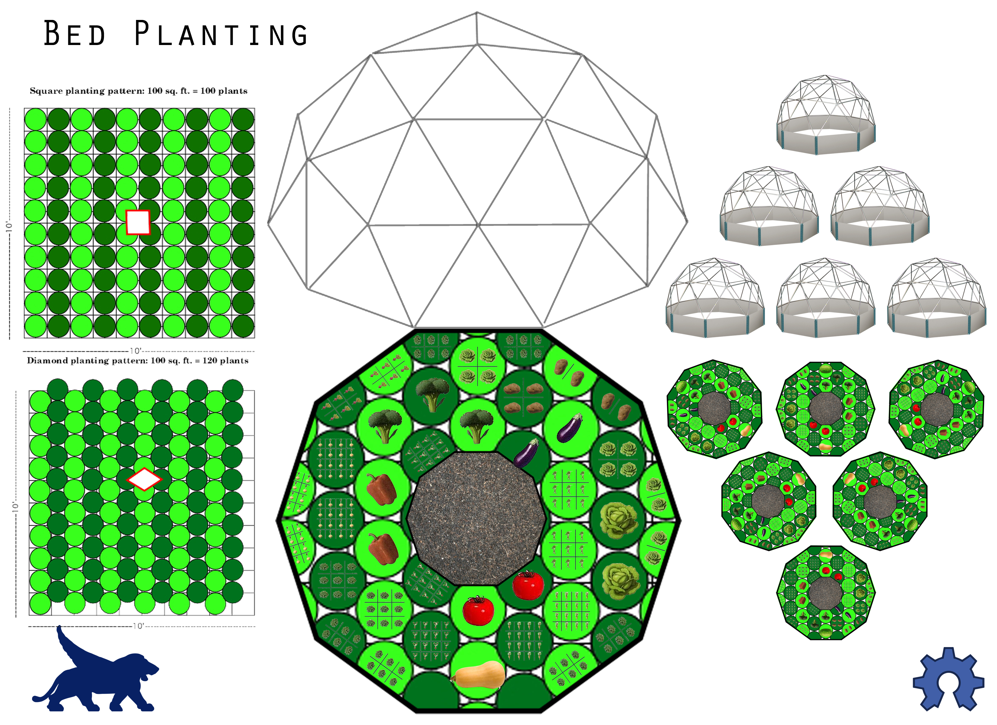
1 Using the Bed Planting image for reference, as well considering additional instructions for increasing the success of a planting, plant the garden bed, following seed spacing instructions found on seed packet.
2 Place the dome in place on top of the bed, with the dome irrigation hose centered over the primary bed plate. Place the control stand next to the bed, with the irrigation box end oriented perpendicular to the primary bed plate. Connect the irrigation hose to the male outlet port at the top of the fertigation tank. Install the irrigation solenoid assembly in the irrigation box. Thread the right solenoid onto the fertigation tank. Pull the main water connection swivel through its port in the irrigation box, before sliding the sheet metal collar down over its neck. Secure the sheet metal in place by placing 4 small metal screw in each of the sheet’s corners. Make a short garden hose (~2.25’), and connect it between the worm bin lid and the [top] brass fixture on the inside of the primary bed plate. Make another short garden hose and connect the top brass fixture on the outside of the primary bed plate to the irrigation solenoid exiting the left side of the irrigation box. Connect the clear ½” vinyl tubing to the outlet barb of the primary bed plate. Run the hose into the side of the irrigation box, under both solenoids, through the opposite end of the irrigation box, and through the 1” porthole drilled in the side of the fertigation cabinet. Leave ~3.5’ of tubing inside the cabinet. Drill a 5/8” hole in the side of the 1 quart container approximately 1” up from the bottom. Place the rubber grommet in the hole. Connect the 1 quart container to the end of the clear vinyl tubing inside the cabinet. Install the aquarium pump inside the cabinet in the top left corner. The aquarium pump should have its air-port facing down. Run the electric cord out the 1” porthole [or 2” porthole if necessary]. Place the bucket in the cabinet, so that it isn’t sitting on the vinyl tubing, and the 1 quart container can be lifted at an angle to poor its contents into the bucket at a later date. Place the submersible pump into the bucket. Connect ~3’ of aquarium pump tubing to the air stone. Place the air stone in the bottom of the bucket and connect the other end of the hose to the aquarium pump. Run submersible pump’s electric cord out of the 1” porthole [2” porthole if necessary]. Make and connect a short garden hose between the submersible pump and the fertigation mixing vessel, with the hose running through the 2” porthole in the top of the cabinet. Install the router in the PVC junction box on the back of the control stand. Run the appropriate amount of each wire through the porthole in the bottom of the junction box, before screwing the top back onto the box. Install the various sensors inside RobotGardener. Moisture sensors are placed in the soil of the garden bed and in the manure in the earthworm bin. Temperature sensors go inside the dome covers (as shaded as possible).and inside the worm bin lid. Additional sensors may also be installed now. 3 Plug all the devices sensors to their various connections: particular electric plugs (RobotGardener main, router, pumps, fans, etc.) , solenoid connections, sensor connections, and internet. You can now make a batch of actively aerated organic fertilizer solution. There are any number of ways to mix this solution to promote varying microorganism populations. Please read Teaming with Microbes by Jeff Lowenfels and Wayne Lewis (www.teamingwithmicrobes.com) to get a strong understanding about the soil-food-web, and how populations of microorganisms interact with plants. We add a couple gallons of clean water to the bucket, and an adequate amount of Garret Juice. Make sure the aquarium pump is on and the solution is aerating. This solution should be used in a timely manner before another batch is made. 4 Once everything has been properly connected a full functions test can be performed.
 What is the OuterBabylon Control Unit
Chapter 1: Warning and Disclaimer
Chapter 2: Possible Community Directions
Chapter 3: Overview
Chapter 4: Electrical Box Preparation
Chapter 5: Build the Heavy Current Router
Chapter 6: Build the Relay Box
Chapter 7: Build the Arduino Project Box
Chapter 8: Build the GIF Power Box
Chapter 9: Modify the Power Strip
Chapter 10: Build the Sensor Patch Bay
Chapter 11: Building the Sensors
Chapter 12: Splicing the Solenoids Onto Plugs
Chapter 13: Completing the Unit
Chapter 14: Helpful Tools
Chapter 15: Parts List
Builder Notes
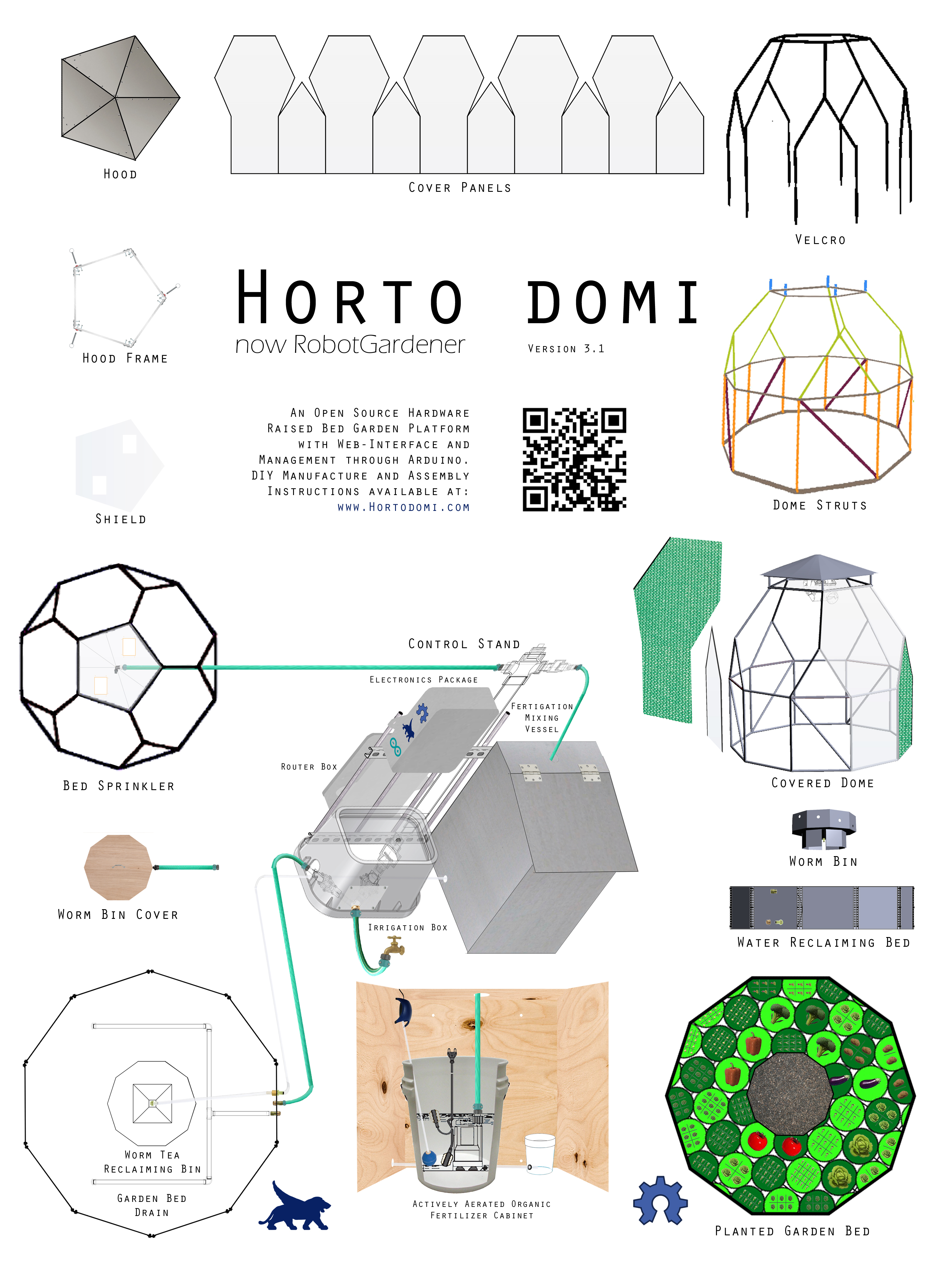
Horto Domi Smart Garden
Control Unit Documentation Version 3
What is the OuterBabylon Control Unit
Chapter 1: Warning and Disclaimer
Chapter 2: Possible Community Directions
Chapter 3: Overview
Chapter 4: Electrical Box Preparation
Chapter 5: Build the Heavy Current Router
Chapter 6: Build the Relay Box
Chapter 7: Build the Arduino Project Box
Chapter 8: Build the GIF Power Box
Chapter 9: Modify the Power Strip
Chapter 10: Build the Sensor Patch Bay
Chapter 11: Building the Sensors
Chapter 12: Splicing the Solenoids Onto Plugs
Chapter 13: Completing the Unit
Chapter 14: Helpful Tools
Chapter 15: Parts List
Builder Notes
Horto Domi Smart Garden
Control Unit Documentation Version 3
design by Samuel Bagot
Doc Ver 0.9 p. 1/63 Table of Contents
Doc Ver 0.9 p. 2/63 What is the OuterBabylon Control Unit
The Control unit is simply a closed box system that controls a list of electrical peripherals by providing a web interface and computer automated programing. We will use this unit to control the watering of a garden with water solenoids and moisture sensors and the temperature with fans and temperature sensors. The control unit is designed to be installed near an outside garden and be weather proof.
Doc Ver 0.9 p. 3/63 Chapter 1: Warning and Disclaimer
Supplemental video: “Chapter 1: Disclaimers and Warnings” at www.YouTube.com
Know:
Work in progress so documentation is going to be more up to date The videos are to help get people started and provide general guidance This project deals with dangerous electrical power and should be taken seriously This project is for adults only All work should be double checked by someone with advanced electrical knowledge of dangerous electrical systems Advanced knowledge of wiring and electrical safety is required to complete this project safely This project should not be attempted by anyone who is unfamiliar with electrical safety. Read the entire document before starting on anything mentioned inside this document. Doc Ver 0.9 p. 4/63 Chapter 2: Possible Community Directions
A control unit like this one can be used in a variety of environments and has many possible directions. It would be nice to see some future projects based off this one or a part of this implementation. It's versatility comes from it's simple core of functionality. It's most basic accomplishments are the following simple tasks:
Remotely turn devices on or off manually through a web interface Turning devices on or off on preprogrammed intervals Turn devices on or off after analysis of analog sensor data Provide data output of analog sensors through a rest web interface Peripherals - This unit can actually be altered to control any number of different types or peripherals. It can be used to control several fluid pumps or more water solenoids. It doesn't have to be used in an outside or garden environment. The concepts and ideas in this project can even be used to control a series of decorative lights or refrigerators in your house. It can be used to automate mechanisms to feed cattle on controlled intervals or remotely on demand through web interfaces or rest APIs.
Sensors – Any number of different sensors can be used. For example, Ph levels are important to gardening and soil. A PH sensor can be utilized to control the injection of chemicals to balance the soil during watering.
Software -Better software can be written with more options on tolerances or to incorporate more sensors. These control units can be made to talk to each other as well to share data or distribute operations. There can also be a central software that can talk to several units. They can be made to scan your home network and identify control units and help conform their configurations as well.
Documentation – This document is periodically updated and revised as typographical errors and unclear sections are identified. Any community help along these lines will be greatly appreciated. Both pdf and doc formats are available for people to download and edit.
Doc Ver 0.9 p. 5/63 Chapter 3: Overview
In this document, we will outline and discuss the basic building of the garden control unit. Below is a big picture outline of what we will detail in this document. There is also companion video to much of this build process at www.HortoDomi.com or www.OuterBabylon.com .
Building the control unit Building the sensors Building the solenoids Installing the software into the Arduino Mounting control unit Running the electronics into the garden Supplemental video: An additional video “Chapter 3: Work Area and Setup” is available on www.YoutTube.com which provides information about our workspace setup and how to apply the project template to the project board.
Doc Ver 0.9 p. 6/63 Chapter 4: Electrical Box Preparation
Parts list:
• 1' x 1' Waterproof Electrical Box • 21/32x12x48 Paint Grade Edge-glued Panel Cut the broad to 11.5” X 11.5”.
Draw the template onto the cut board.
Doc Ver 0.9 p. 7/63 Keep in mind that the above template is not completely drawn to scale so that the text measurements can be larger and more readable. The measurements are simply suggested distances from the side of the project board so that all the components will fit in the end.
Lay the cut board into the large electrical box once to make sure that every thing is going to fit in the end.
Drill the holes in the box. For this we will need to drill a hole in the bottom of the box that is approximately 2” wide. This will most likely take a special drill bit. All external cables for power and sensors will run through this water-resistant hole.. I positioned the hole so that it has a margin of 1” from the eventual backside of the box and a margin of 1” of the eventual right side.
Also, it is best to make sure that you choose the correct side to be the bottom. So choose a side of the big electrical box that doesn't have a plastic ear for bolt mounting to be the bottom. We will want the two sides with bolt ears to be the left and right sides so it can be mounted to a couple of stakes later.
The smaller holes just need to be in two parallel columns as centered as possible. These smaller holes will be how we will zip tie the incoming and outgoing cables.
The final box should look similar to the picture. Note the bolt mount ears on sides other than the side you chose to be the bottom.
Doc Ver 0.9 p. 8/63 Chapter 5: Build the Heavy Current Router
Supplemental video: “Chapter 5: Build the Heavy Current Router” at www.YouTube.com
Parts list:
Breaker Box Breaker Box Lid Wire Screws 4 x Extension cords 15' 3 x NM/SEU Cable Connectors 3/4” 24V .65A power supply from the garden timer Mark your breaker box.
Break out the proper holes.
Insert and screw in the cable connectors.
Doc Ver 0.9 p. 9/63
Cut the 4 extension cords:
Chop the four 15' extension cords into three lengths. These three lengths will be an 11' length with the female terminal still attached, a 2' length with two cut wire ends, and a 1' length with the male terminal still attached. Below is a description of the length and what they will be used for.
For solenoid 1 peripheral - chopped 11' female length to go to the solenoid 1 outside of the control unit. For solenoid 2 peripheral - chopped 11' female length to go to the solenoid 1 outside of the control unit For fan peripheral - chopped 11' female length to go to the fan outside of the control unit For light/pump peripheral - chopped 11' female length to go to the light or pump outside of the control unit
For solenoid 1 relay- chopped 2' cable from high voltage router to relay For solenoid 2 relay- chopped 2' cable from high voltage router to relay For fan relay- chopped 2' cable from high voltage router to relay For light relay- chopped 2' cable from high voltage router to relay
For solenoid 1 splice - chopped 2' male extension to go from power strip to the high voltage router For solenoid 2 splice - chopped 2' male extension to go from power strip to the high voltage router
For fans power - chopped 2' male extension to go from power strip to the high voltage router For light/pump power - chopped 2' male extension to go from power strip to the high voltage router For solenoid power- the 24V .65 Amp converter to go from power strip to the high voltage router
Doc Ver 0.9 p. 10/63
Pull the wires through the appropriate holes in the high voltage router and connect them using the wiring diagram. Start with the solenoids. Remember that some wire nuts involving the solenoids will have three wires and all others will have two. This is because both solenoids will branch off each of the wires from the power supply. Make sure that the wire nuts are tight and that no bare wire is visible around the bottom edges of the wire nuts once they are on. Shorts can not be risked in this portion of the construction.
Continue with the same methodology of connection the wires with wire nuts to accomplish the wiring diagram for the high voltage router. Complete the light circuit and then the fan circuit.
Now to test the high voltage router, you must temporally cap off each of the four cable pairs coming out that will go to the relay shield from the port labeled “relay out”. This will simulate all of the relays being turned on and closing their corresponding circuits. Again this allows all electricity to flow through the circuit and this needs to be done on a clean non-electrically conductive table with hand and tools away from the high voltage router. p. 11/63
This test requires that you have a power strip with the power control in the off position and the high voltage router completely closed with its breaker box lid. You will plug in a light bulb into a peripherals female extension coming out of the router and plug the male counter part into the power switch. With your hand away from the work area, you will turn the power strip on to see if electricity goes to the light bulb. If it does then repeat the test for the next peripheral until they are each tested.
If one peripheral route doesn't produce the light turning on, then everything must be unplugged from power sources and male and female ends and the high voltage router must be opened and the circuit rebuilt. Remember that the solenoid tests should produce a light from the bulb that is significantly weaker since the amperage of the solenoid power supply is much lower than the other peripherals.
Screw close the breaker box.
Doc Ver 0.9 p. 12/63 Chapter 6: Build the Relay Box
Supplemental video: “Chapter 6: Build the Relay Box” at www.YouTube.com
Parts list:
Breaker Box Breaker Box Lid Seeed Studio Relay Shield Signal Wiring 3 x NM/SEU Cable Connectors 3/4” 2 x longer wood screws Prepare the router box by labeling one port “high voltage in” and one port “ signal in” as indicated in the picture below. Break out these two port holes so that you can later route wire through them.
Insert and screw in the NM/SEU cable connectors into the port marked “high voltage router”.
Doc Ver 0.9 p. 13/63
Set the breaker box aside.
Strip off a two small wire lines that can carry a 9V and Ground current.
Attach one, preferably a wire with a line or dashed line down it's side indication ground, to the Ground terminal on the relay shield.
Attach one, preferably a wire without a line or mark on its side, to the 9V terminal. This will power the relay shield. The other end of this wire will run to the signal patch bay in a future step to supply power from the Arduino power supply, through the Vin power circuit, so that it doesn't have to be pulled from the power being used to run the Arduino itself.
Doc Ver 0.9 p. 14/63
Strip four more signal cable wires so that they can be soldiered to the relay shield on one side and soldered onto the Arduino on the other side.
Attach the signal cables by soldering four signal wires onto the relay shield board as show in the positions labeled D0, D1, D2, and D3. Make sure that these are about a foot long each because they will need to go out of the relay shield box and into the Arduino and have some space to be soldered onto the Arduino. p. 15/63
Clean up any tall or misshapen solider connections on the back to prevent any shorts or misdirection of electricity.
In my example I cut a small groove through the breaker box into the port for the signals so that I can have more options on routing these signal wires and power wires out to the Arduino and the patch bay. Just keep it in mind.
Doc Ver 0.9 p. 16/63
Route the high voltage relay lines from the high voltage router through the appropriate port on the relay shield breaker box. Do not tighten down the cable connector clamp on the relay shield breaker box until the relay lines are later secured in a relay terminal.
This is a relay terminal port. Observe it closely and note what each port on the terminal is labeled as. We are going to fully avoid any port with “NC” in the label. p. 17/63
Below is how we will route the peripherals into the relay shield terminals.
Secure each of the four pairs of wires from the high voltage router into a terminals as indicated by the table above.. IMPORTANT: NEVER CONNECT ANYTHING TO ANY RELAY TERMINAL PORTS HAVING “NC” IN THEIR LABEL. NC means “normally closed” and allows electricity to travel through the circuit when the relay is not engaged. This is definitely not what we want and must be insured not to happen. Once each of the four wire sets is secured into a terminal set, go back through and look closely to make sure that you didn't accidentally attach any wires to any ports having “NC” in their labels. The proper two ports to use on any given terminal are the “COM” and “NO”. NO means “normally open” and only allows electricity to travel through the circuit when you have properly engaged its corresponding relay. This is what we want.
Once all four of the wire pairs from the high voltage router are properly secured into “NO” and “COM” ports of relay terminals, check to see the on “NC” terminal ports were used and make sure that each of the terminal port screws are as tight as you can get them without breaking the port.
Doc Ver 0.9 p. 18/63 Then, lightly pull the wire pairs back through the breaker box port until a comfortable amount of wire is left inside the relay breaker box. Then tighten down the cable connector clamp to keep the wires in place inside the relay shield breaker box.
You may want to put a small screw into the relay shield through one of the proper holes so that it doesn't move around but I leave mine floating. Now route the signal and power wires out of the relay shield breaker box and close the lid. TODO: write more on the testing of the relay shield.
Test the relay shield with the high voltage router and the Arduino plugged in. Make sure that your signal paths and high voltage routing through the relay shield is proper to produce the proper relay reactions listed in the chart below.
Once everything checks out. Mount the relay shield on top of the heavy current router and to the project board. Do this by placing 2 screws through opposing corners of the breaker boxes. The same screw will go through the mounting hole on the top relay shield breaker box, through the same mounting hole on the heavy current router breaker box, and then into your Doc Ver 0.9 p. 19/63 p. 20/63 project board into it's appropriately marked spot from the template.
Chapter 7: Build the Arduino Project Box
Supplemental video: “Chapter 7: Build the Arduino Project Box” at www.YouTube.com
Parts list:
Electronics Project Box Arduino Signal wire Spacer for Arduino 2 x small wood screw 9V .65A Arduino power supply Cut a hole towards one side for the relay signals to be pulled through. The suggested cutting pattern is depicted below.
Cut another larger hold at one end for the power wires, sensor wires, Ethernet cable, Arduino power cord, and USB computer cord. The suggested cutting pattern is depicted below.
Doc Ver 0.9 p. 21/63
Next we are going to solder the sensors wires, power wires, and the digital out wires that go to the relay shield. We'll end up with something like this:
So, next, you should cut 7 one foot lengths of the stranded signal cable for the sensors. This will include 5 signals for the moisture sensors and 2 signals for the temperature sensors. These wires are going to be ran to the signal patch bay in the future once it's completed.
Also, you will want to cut 3 more one foot lengths of the stranded signal cable for routing some low amperage electricity to the signal bay bay as well. These wires include a 3.3V to fuel the temperature sensors, a 5V to fuel the moisture sensors, and a ground for many components.
Begin by heating up your soldering iron and soldering the 7 sensor signal wires to the bottom of the Arduino. The pins that this project uses are analog output pins. The 2 for the temperature sensors are A8 and A9. The pins for the moisture sensors are pins A11, A12, A13, A14, and A15. Don't hold the soldering iron to the metal for more than three or four seconds without pulling it away and letting the board cool. It's pretty easy to burn a PCB board like an Arduino.
Doc Ver 0.9 p. 22/63 If you are uncomfortable soldering onto your actual Arduino board then you can also place the wires into the top slots of the Arduino. I did this for some of my first models, but the connections can sometimes wiggle out and are generally less stable.
Repeat this process to attach the 3.3V, 5V, and ground wires onto the Arduino board.
Next you will want to take our previously completed relay shield with its four relay signal wires and attach them in the same way to your Arduino board. The attachment pattern is shown in a table below. Attaching them in this configuration will ensure that community code can control your smart garden correctly.
Make sure that you run the relay shield signals out of the appropriate port on the relay shield breaker box. This is hard to reverse once the signal lines are soldered to the Arduino board. If you have cut a small slot from the top of your relay shield breaker box down into the relay signal port on that box, then you can later slide these new cables into place.
Peripheral Arduino Digital Relay Shield Input Pin Signal Port
Solinoid 1 31 D0 Solinoid 2 33 D1 Light 35 D2 Fan 37 D3 Doc Ver 0.9 p. 23/63
Put spacers of some sort under the Arduino mega so that it doesn't rest on the bottom of the project box.
Take a small wood screw and tack down the Arduino to the project box and the project board. Make sure that you do this through the small mounting hole that is cut in the back of the Arduino board closest to the analog signal ports. This is because there are more critical components close to some of the other mounting holes on the Arduino Mega, and we don't want to short or disrupt those components.
Doc Ver 0.9 p. 24/63 TODO: Test the Arduino and the relay shield setup.
Keep track of the lid to the box and the screws that will hold it in place. p. 25/63 Chapter 8: Build the GIF Power Box
Supplemental video: “Chapter 8: Build the GIF Power Box” at www.YouTube.com
Parts list:
GFI power socket small one socket electrical box Long outdoor extension cord NM cable Connector Clamp 3/8” trade size 1/2” knockout small wood screw Some how I didn't get decent pictures of this process through any of my builds, but this will be the final product. There is nice video help with this if you want more direction of course.
Chop the big extension cords female side off with a foot left on the female end. This should produce a really long cord with a male end. The GFI outlet will become the new female end of this extension cord.
Break out a port hole on the single socket electrical box for the chopped end of the extension cord to enter. Preferably the port that you want to break out is one on the top or bottom so that the cord will have a little more space to enter the single socket electrical box. Add the NM cable connector clamp into the port that you just broke out.
Run the cut end of the long extension cord into the power box through the broken out port hole. Add GIF to the end of the cut cord by inserting the colored individual wires from the cord into their appropriately marked ports on the back of the GFI unit.
Mount this single socket electrical box to the board with a small wood screw according to the board template that we have drawn onto the board. I found it pretty easy just to drill the screw through the back of the socket box and then into the board.
Mount the GFI into the single socket electrical box with the two screws that are based in the GFI. Then add face plate to the front of the GFI unit and it should start looking more like a wall socket.
Now secure the input power cord in the input port by clamping down the NM cable connector. The point of this of course is to make sure that nothing that pulls on the cord will pull on the GFI connections into the single socket electrical box.
Press the test button on the front of the GFI.
Doc Ver 0.9 p. 26/63 p. 27/63
Chapter 9: Modify the Power Strip
Supplemental video: “Chapter 9: Modify the Power Strip” at www.YouTube.com
Parts list: • Power Strip Warning: This part of the project is simply to make the cord shorter on the power supply. It is not completely necessary as the extra cord can hang outside the box through the wire input port on the bottom of the box. This modification must be done correctly. Please read through the section of this document called “Chapter 1: Disclaimers and Warnings” and review the supplemental video that goes along with that chapter. Make sure the power strip is not plugged in for this section. Open up the power strip by unscrewing the backing screws and popping the backing plate off.
Remove the screws and collar that hold the input power cord in place
Doc Ver 0.9 p. 28/63
Pull out the input power cord and remove the guts of the power strip.
Make sure to take a picture of all angles of the soldiered connections inside the power strip so that you can solder new connections appropriately for your model of power strip. This is important and confusion here will produce shorts and potentially dangerous results.
With a heated soldering iron, remove the soldered leads that connect the power cord to the power strips internal circuitry. Doc Ver 0.9 p. 29/63
Trim any extra solder from the back of the guts to prevent shorts.
Once the cord is removed, cut it to about a length of two feet with the male connection end still attached to the two foot length. p. 30/63
Consult your picture of the complete unmodified power strip to reattach by soldering the shorter cord.
Replace the guts into the power strip frame. p. 31/63
Replace the screws and collar that held the input power cord into place.
Replace the back and screw in the backing screws to the power strip.
p. 32/63 p. 33/63
Chapter 10: Build the Sensor Patch Bay
Supplemental video: “Chapter 10: Build the Sensor Patch Bay” at www.YouTube.com Parts list: 2 X 12 Position Barrier Strip Euro Terminals 1 X 10K Ohm Resisters ¼ Watt First, check out the wiring diagram included in this project to see how we are going to wire this component up. The wiring diagram can be found at www.HortoDomi.com or www.OuterBabylon.com.
I will refer to the back of the sensor patch bay as the side that all the wire will plug into which come from the inside of the control unit. These wires include the wires coming from the Arduino.
I'll refer to the front of the sensor patch bay as the side that includes all the inbound wires like the sensor signal wires from outside the control unit.
Note how the ground and Vin lines are looped through several back end port holes in one of the Euro terminals on the wire Doc Ver 0.9 p. 34/63 diagram. This is so that there are more spots on the front of the patch bay to connect things that require th power and ground. For this, we will need to make some little metal connectors for the back of the sensor bay like the following.
Next, wire up the voltage divider according to the wiring diagram. This is the part of the sensor patch bay that requires the two 10 ohm resistors and the 3.3V input power.
Then, run the five analog sensor lines into the back of the sensor patch bay for the five analog ports that will read the moisture sensors. p. 35/63
Mount the Euro terminals onto the board where the template specifies and we'll be done with the work in this section Later, we will run the sensors cords into the box and into the front of the sensor patch bay. For now though, we will wait to finish the unit because it's easier to add in the sensors once the unit is complete. p. 36/63 Chapter 11: Building the Sensors
Supplemental videos:
“Chapter 11 - A: Building the Sensors” at www.YouTube.com “Chapter 11 - B: Wire Stripping” at www.YouTube.com “Chapter 11 - C: Building the Temperature Sensor” at www.YouTube.com “Chapter 11 - D: Hooking Up A Sensor” at www.YouTube.com Todo: Make sure that parts list items match the master parts list items titles Parts list:
2 X 1/4” - 1/8” Heat Shrink Tubes 2 X 10K Precision Epoxy Thermistor 5 X Vegetronix Soil Moisture Sensor - 2 meter cable 1 X Cat3 Cable – 250' 1 X Roll of Electrical Tape 1 X Liquid Electrical Tape Cut 7 lengths of Cat3 cord and wrap them neatly so that they are manageable.
Strip the ends of five of them and cut out some of the inner wires so that there are only three wires left. We will use these five cords to extend the moisture sensors. When you do this, you will want to choose the same three colors of inner wires to preserve so that we can map these colors to the colors on the moisture sensors and temperature sensors. For instance, possibly chop the cord down to a red (Vin), green (ground), and blue (signal) inner wires so that they can easily be mapped to the actual sensor wires that are red (Vin), uninsulated (ground), and black (signal).
Doc Ver 0.9 p. 37/63
Strip the ends of the other two of them and cut out some of the inner wires so that there are only two wires left. We will use these five cords to extend the temperature sensors. Choose the same colors and do the proper color matching as you did with the moisture sensors above.
Go through each exposed wire on each of these seven cords and strip the wires down to metal. Expose about a third of an inch of metal on each wire.
One end of each of these seven cords will be soldered to a sensor so we can go ahead and add a piece of shrink wrap now to each in preparation for when the soldering is done and we seal the new cord.
Carefully go through each of the seven cords and solder the proper sensors onto the exposed wires. Seal each individual wire with a small wrap of electrical tape.
Doc Ver 0.9 p. 38/63 Once your done adding all the sensors to the cords, move the heat shrink wrap into place and heat it with a lighter until it securely seals the new cord.
Put these seven extended sensors to the side for when we are ready to do the install later. They will be one of the last things that we add to the control unit. p. 39/63 Chapter 12: Splicing the Solenoids Onto Plugs
Supplemental video: “Chapter 12: Splicing the Solenoids Onto Plugs” at www.YouTube.com
Parts list:
2 X 1” FNPT In-Line Jar Top Water Solenoid 2 X Male cord ends that were saved from chapter called “Build the heavy current router” add electrical tape liquid electrical tape 1/4” - 1/8” Heat Shrink Tubes In this section, we are going to splice the water solenoids into a male plug so that we can plug them into the peripheral extension cords when we are doing the final install. This is just a simple splice job where we will just striping the ends of the solenoid wires and soldering them onto a male plug.
The reason that these water solenoids are 24V 0.65A and require a special wall adapter is because electricity is less dangerous when the current is low. The typical setup for household electrical circuits is 110V and 15A - 20A. Since these solenoids are going to be around water and the ground around them may be wet, we have chosen water solenoids that will be much lower amperage and therefore less dangerous if they short out or arc into a user. If it happens to shock you, it will be a small buzz and there is no harm involved where as a higher current may hurt you.
Before you start soldering, remember to place a piece of heat shrink wrapping around one end of the cord you are about to solder. This is so that you can simply slip the shrink wrap down and secure it once the soldering job is done. If you forget this, then there will be no way to get the shrink wrap on once the soldering is done.
Doc Ver 0.9 p. 40/63
Now solder the two wires together but do not heat seal the shrink wrap yet.
Once you are done with the soldering, you'll have to insulate the two wires from each other with two simple wraps of electrical tape. Just make sure that there is no exposed metal from the solder job that could potentially arc out or short from wire to wire.
p. 41/63
Now add a little liquid electrical tape on top of the electrical tape that you just wrapped around the two wires. The liquid electrical tape is so that a fairly secure seal will result when the final heat shrink wrapping squeezes the soldered wires.
So far we have soldered the two wires, wrapped them with electrical tape, and added water proof liquid electrical tape as moisture sealant. Finally, before the liquid electrical tape dries, we will slide the heat shrink tubing over the solder point and secure it by running a flame over it.
p. 42/63 Once this is complete, you will have sealed the cord, and it should look something like the following.
This is what you should end up with. These are ready to plug into the female extension cords that will come out of the bottom of the control unit.
p. 43/63 Chapter 13: Completing the Unit
Supplemental video:
“Chapter 13 - A: Completing the Unit” at www.YouTube.com “Chapter 13 - B: Notes on Debugging” at www.YouTube.com “Chapter 13 - C: Simple Systems Test” at www.YouTube.com Doc Ver 0.9 p. 44/63 Chapter 14: Helpful Tools
Wire strippers Soldering Iron Solider Solider stand with magnifying lens Wet sponge for cooling the soldering iron Silicon or liquid electrical tape to seal any connections from moisture like the water solenoids Drill Drill bit for Phillips screws Drill it for small pilot holes in wood and electrical box Power screw driver Power screw driver charger Exacto knife Small screw driver for Phillips Needle nose pliers Exacto knife Dremil tool with circular disk bit Tool box
Doc Ver 0.9 p. 45/63 Chapter 15: Parts List
This is the suggested parts list. My parts mostly came from on-line sources, Lowe's, and Radio Shack. p. 46/63 1 X Arduino Mega ADK Board Rev3 – Online $50.42
1 X Arduino Ethernet Shield R3 – Online $34.02
p. 47/63 1 X Seeed Studio 4-Channel Relay Shield for Arduino – Online $19.95
1 X 21/32x12x48 Paint Grade Edge-glued Panel – Lowe's $6.85
p. 48/63 1 X 16 Gauge Lawn & Garden Cord – Lowe's $22.97
1 X 1000 Joules 6 Outlet Power Cord + Surge Protector – Lowe's $17.95
p. 49/63 4 X 16 Gauge 13 Amp Brown Indoor Light-Duty Cord – Lowe's $3.97
1 X 16 Gauge 13 Amp Indoor Light-Duty Cord – Lowe's $4.4.7
p. 50/63 1 X Wire Twist Nuts 25pk #18 - #14 – Lowe's $3.95
1 X Ground Fault Circuit Interrupter – Lowe's $15.98
p. 51/63 1 X 12CI 1G Romex Handy Box Old Work Breaker Box – Lowe's $0.83
1 X NM Cable Connector 1/2” Knockout – Lowe's $0.36
p. 52/63 2 X 2 Gang Blank Breaker Box Cover – Lowe's $2.55
2 X WP 2G T Breaker Box - Lowe's $8.17
p. 53/63 4 X ¾ NM/SEU Connector – Lowe's $1.02
1 X 22 Gauge Stranded Hookup Wire – Radio Shack $8.49
p. 54/63 2 X 12 Position Barrier Strip Euro Terminals – Radio Shack $3.49
1 X 10K Ohm Resisters ¼ Watt – Radio Shack $1.19
p. 55/63 1 X 7x5x3 Project Enclosure – Radio Shack $6.99
2 X 1/4” - 1/8” Heat Shrink Tubes – Radio Shack $2.16 p. 56/63
1 X Cat3 Cable – 250' – Lowe's $31.47
2 X 10K Precision Epoxy Thermistor – Online $4.00 Doc Ver 0.9 p. 57/63 p. 58/63
5 X Vegetronix Soil Moisture Sensor - 2 meter cable – Online $34.
2 X 1” FNPT In-Line Jar Top Water Solenoid – Lowe's $10.26
p. 59/63 1 X 4 Station Dual PGM Timer – Lowe's $19.97
2 X 5 1/2” Clamp Light – Lowe's $6.68
p. 60/63 1 X 75W Light Bulbs – Lowe's $4.98
1 X 1' x 1' Waterproof Electrical Box – Lowe's $33.60
p. 61/63 1 X Roll of Electrical Tape – Lowe's $4.89 Todo: Get picture of tape 1 X Liquid Electrical Tape Todo: Get picture of liquid electrical tape p. 62/63 Builder Notes
This is a section for the user to record notes about their specific build and implementation for future reference.
Doc Ver 0.9 p. 63/63