Problem Statement/ Functional Need
Cultivation only requires the movement of small amounts of soil, therefore very little power output. Small tractors are hard on the body of the farmer, cause soil compaction, cost large amounts of money, are complicated to fix, and provide significantly more power than is needed for many seeding and cultivating jobs. Cultivation with a pedal powered machine provides sufficient power, a less physically damaging experience for the operator, and is more environmentally sustainable.
Here is a blog post about the design process of the Culticycle, linked to the WBM.
Functional Description
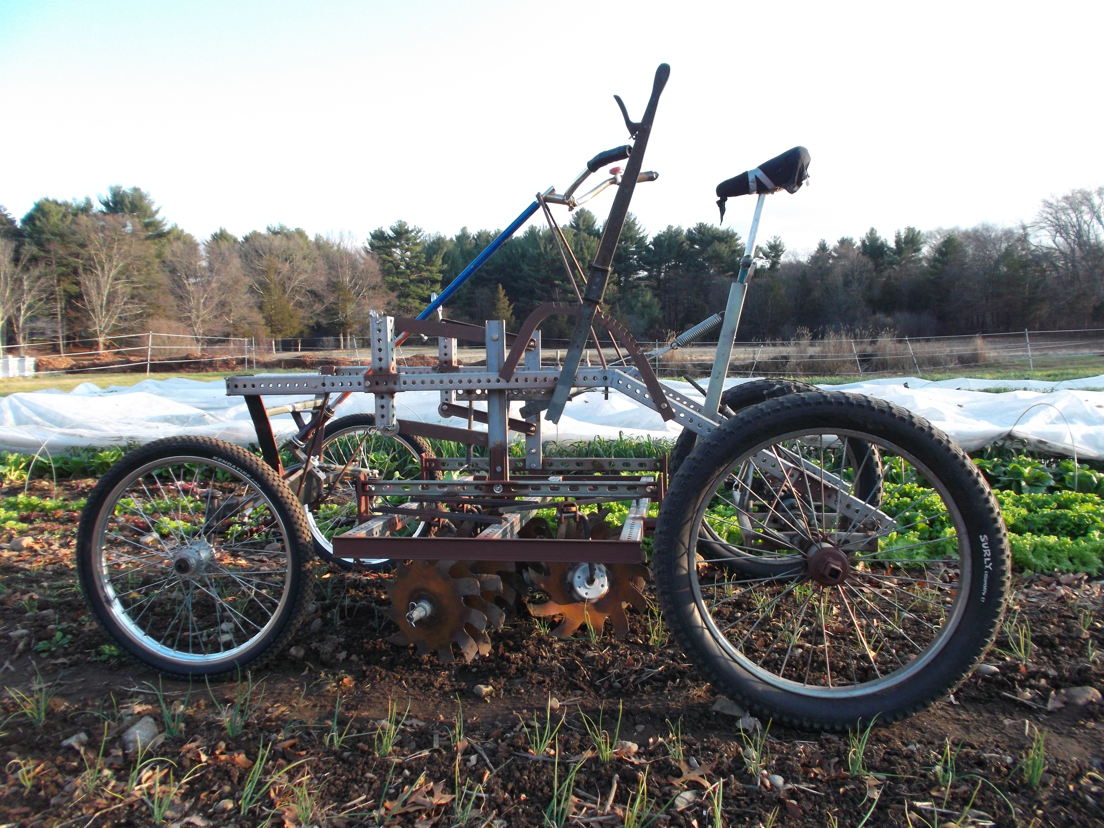
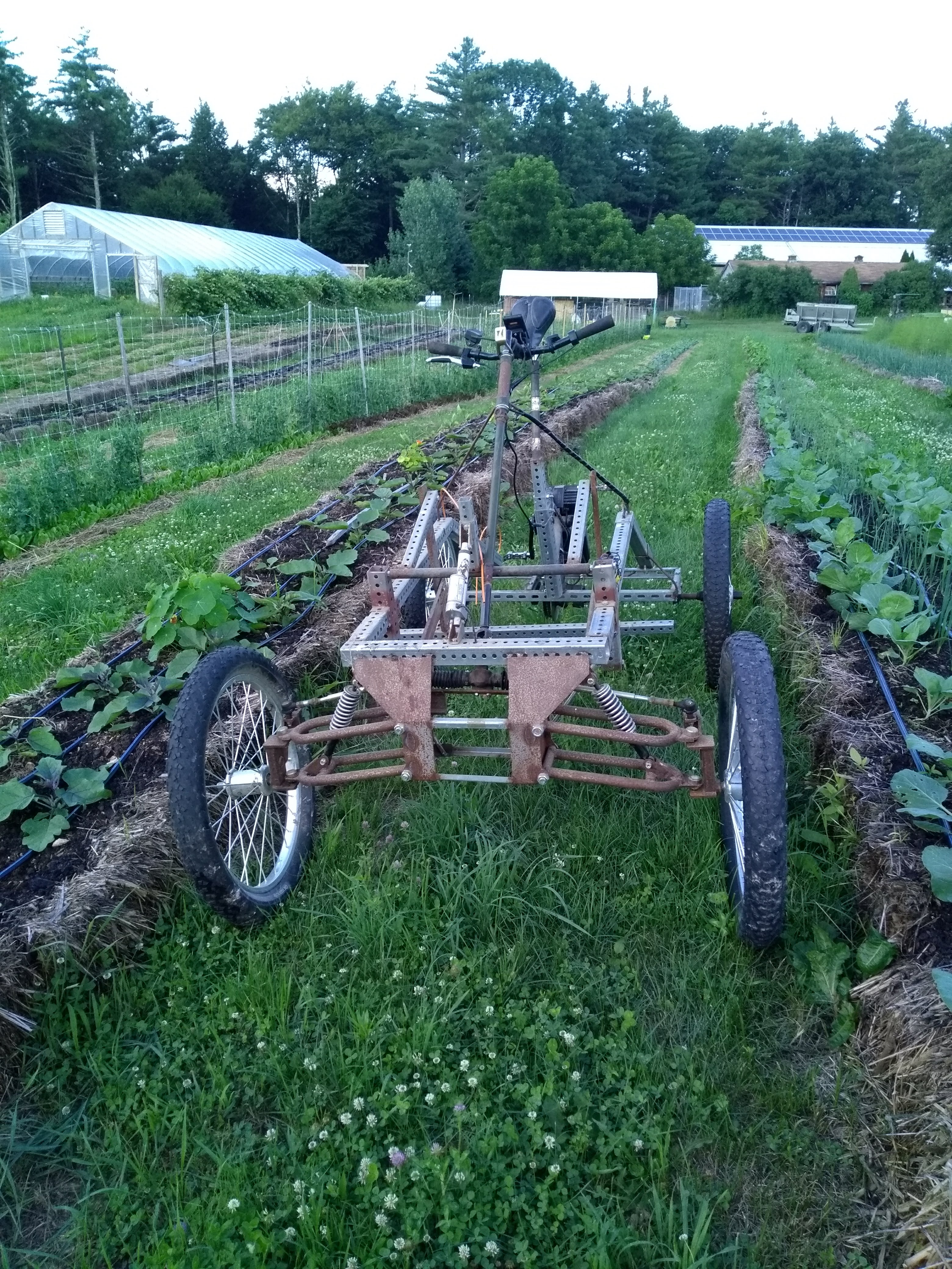
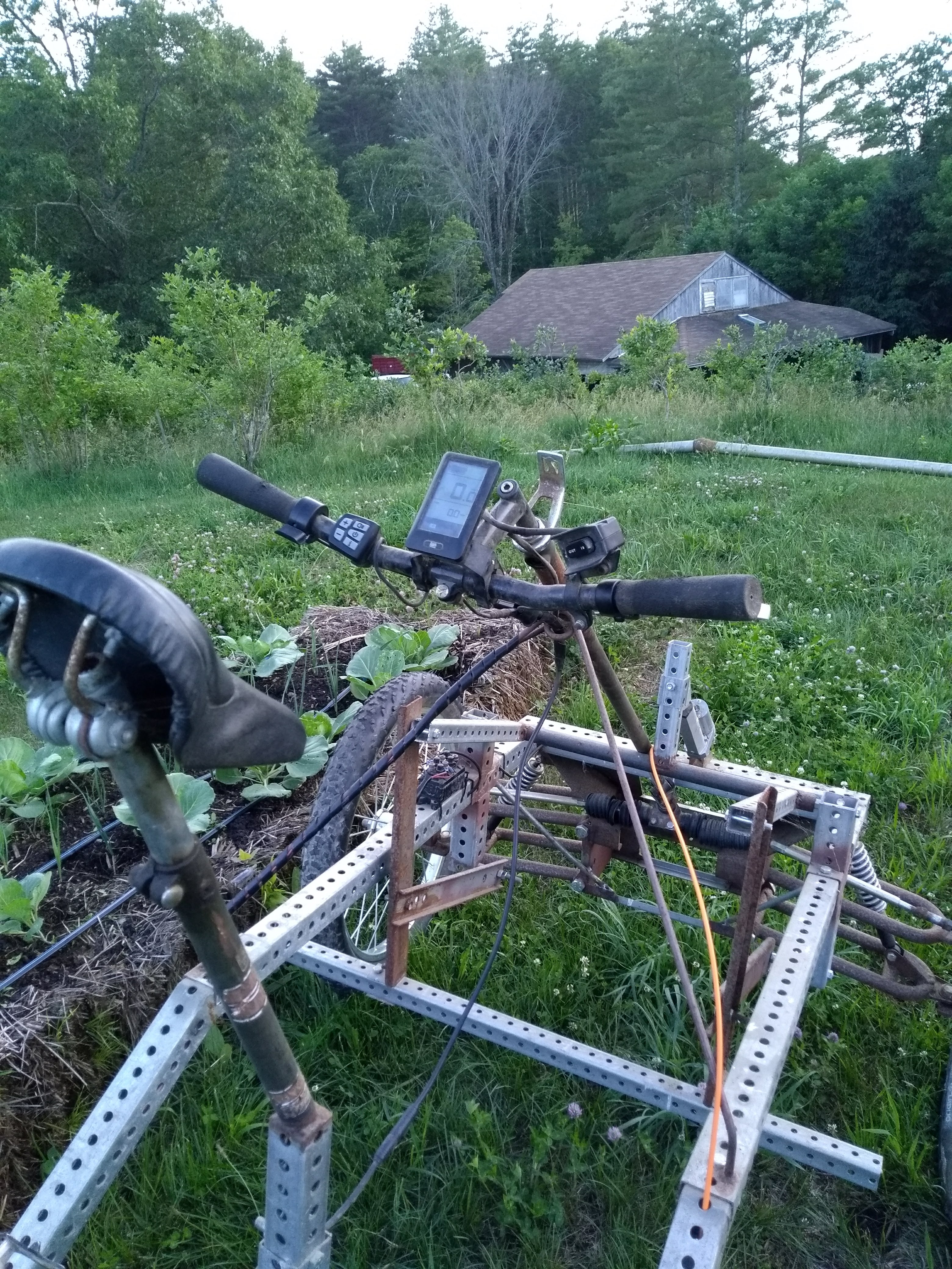
The culticycle is a pedal powered machine, consisting of 2 bicycle front ends, 1 bicycle rear end, a small differential, a tubular steel frame, and a belly mount used to raise and lower cultivating implements, that can seed, flame weed, or cultivate in low horse power situations. The culticycle attempts to show that human pedal power can do some jobs of small tractors, albeit in twice the time, and that the design can be simple enough that no extra weight is needed for traction. The effort required is similar to climbing a 10 degree slope on a seventies Schwinn 3 speed.
This is the first prototype, built by greentractorfarm. Video on YouTube.
This is the second prototype, built by greentractorfarm, with the basket weeder, seeder, and sweeps attached. 2nd video on YouTube.
A birds eye view of culticycle operation. 3rd video on YouTube.
Here are 2 culticycles working on farms with star hoes, flextines and a ground driven brush hoe. 4th video on YouTube.
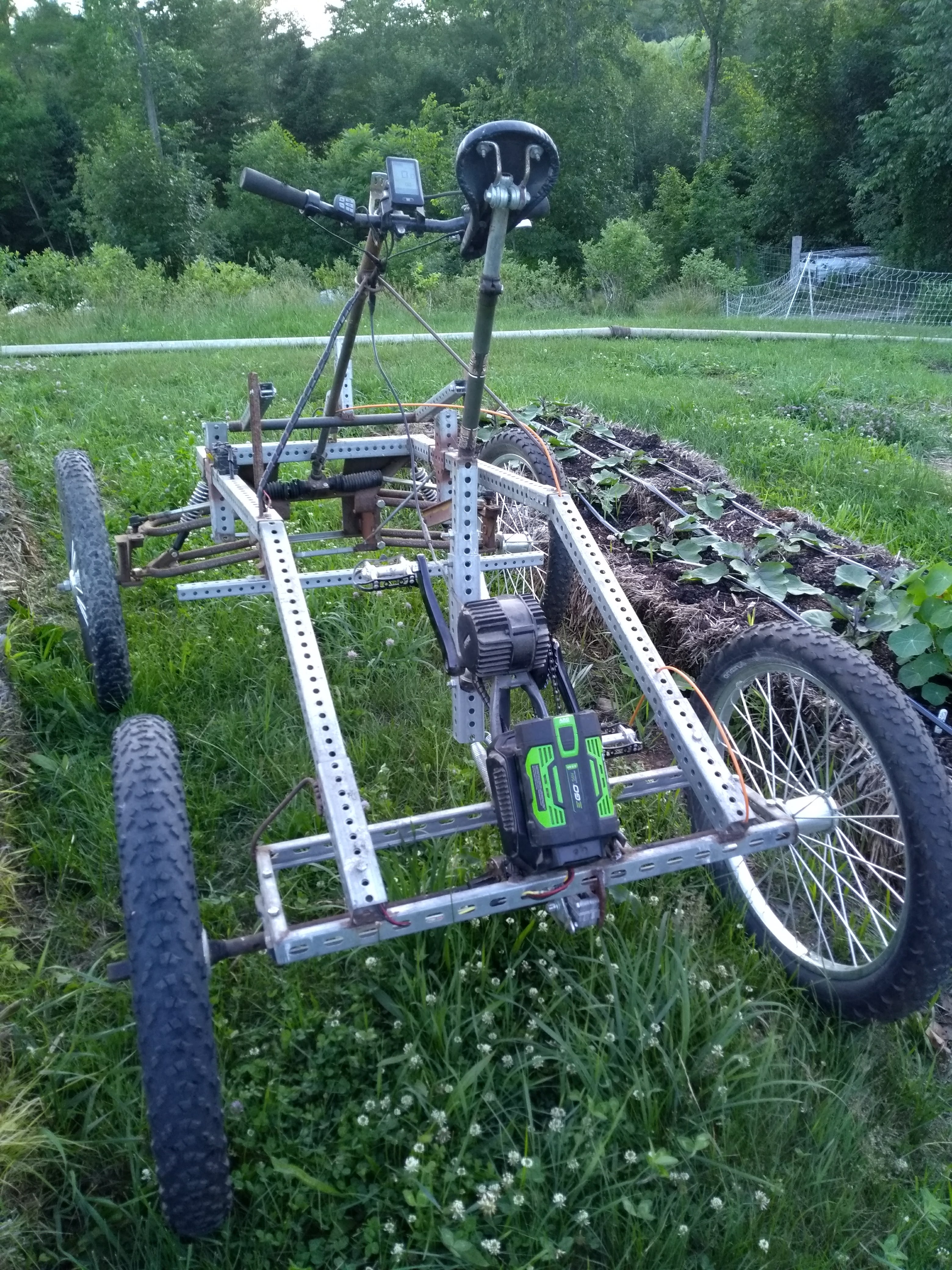
Here is a fat tire version with a counterbalance on the lift. 5th video on YouTube.
Bill of Materials and Sourcing
This prototype consists of:
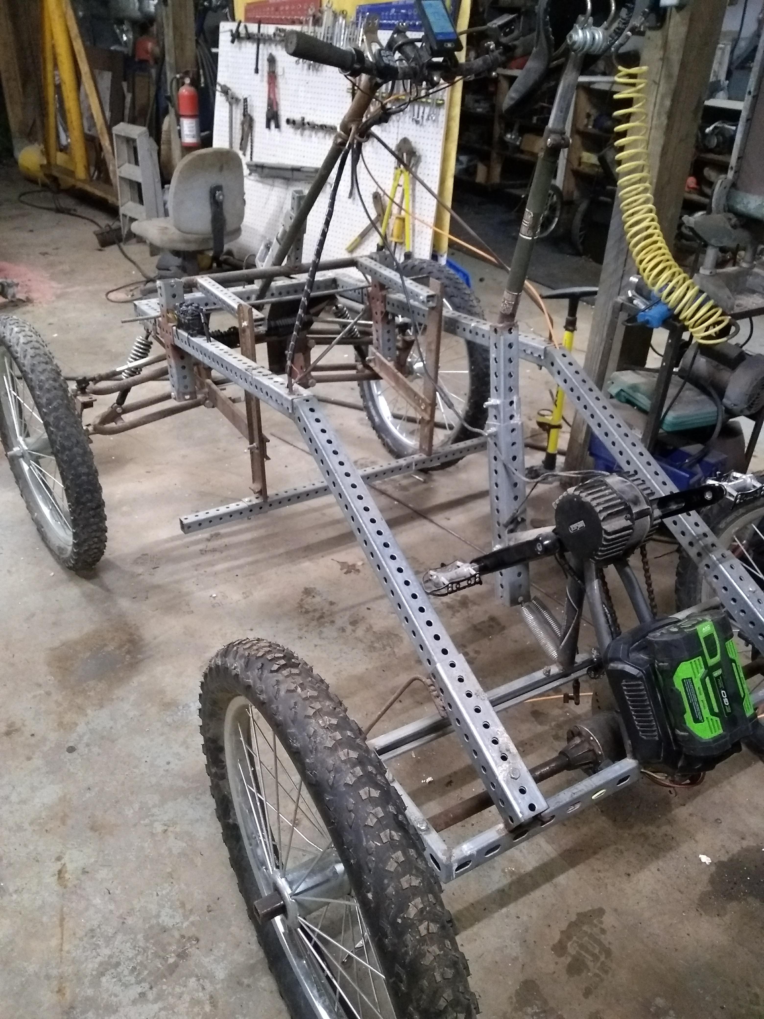
- the front ends of 2 bikes welded together at 42” on center;
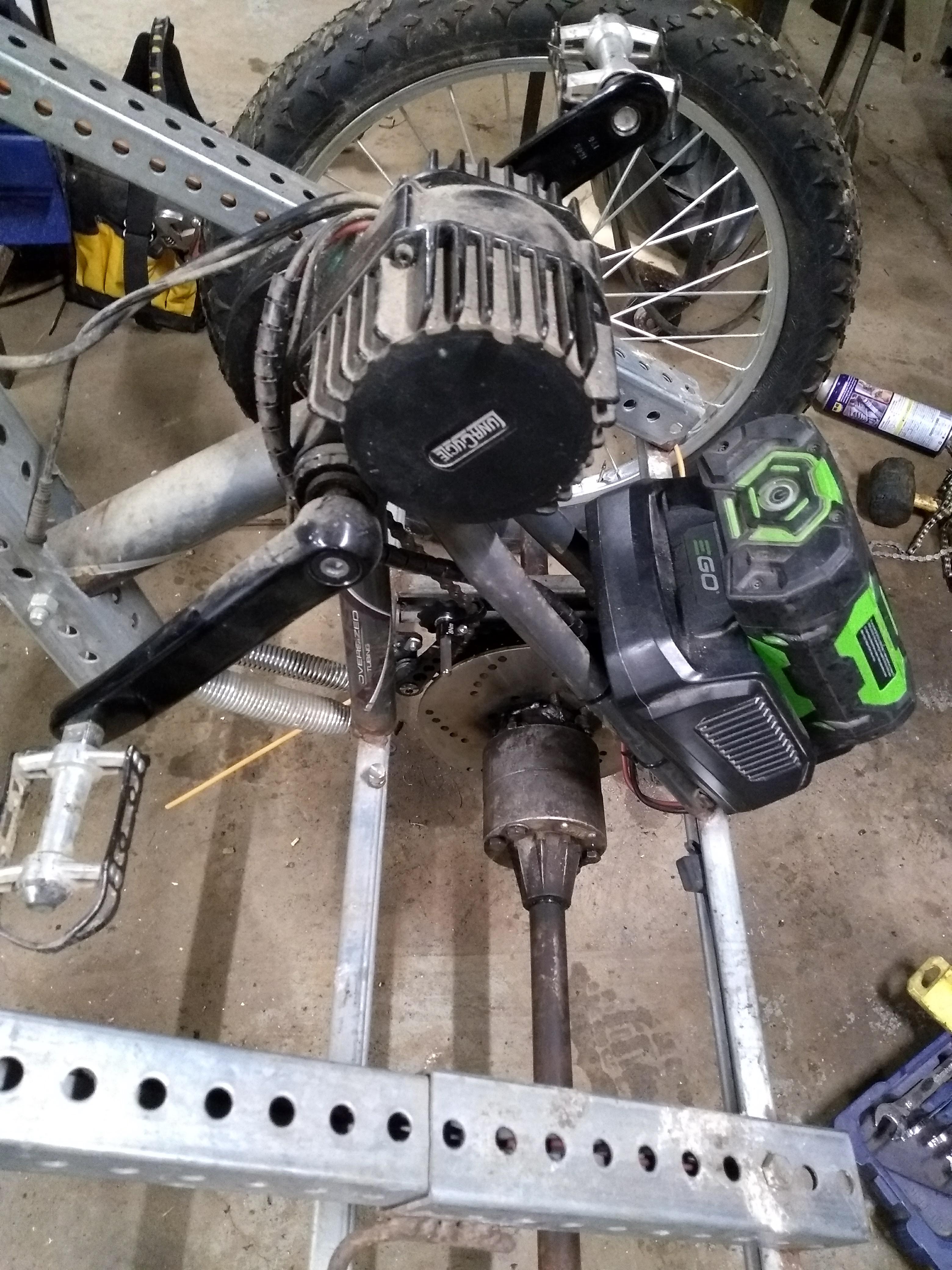
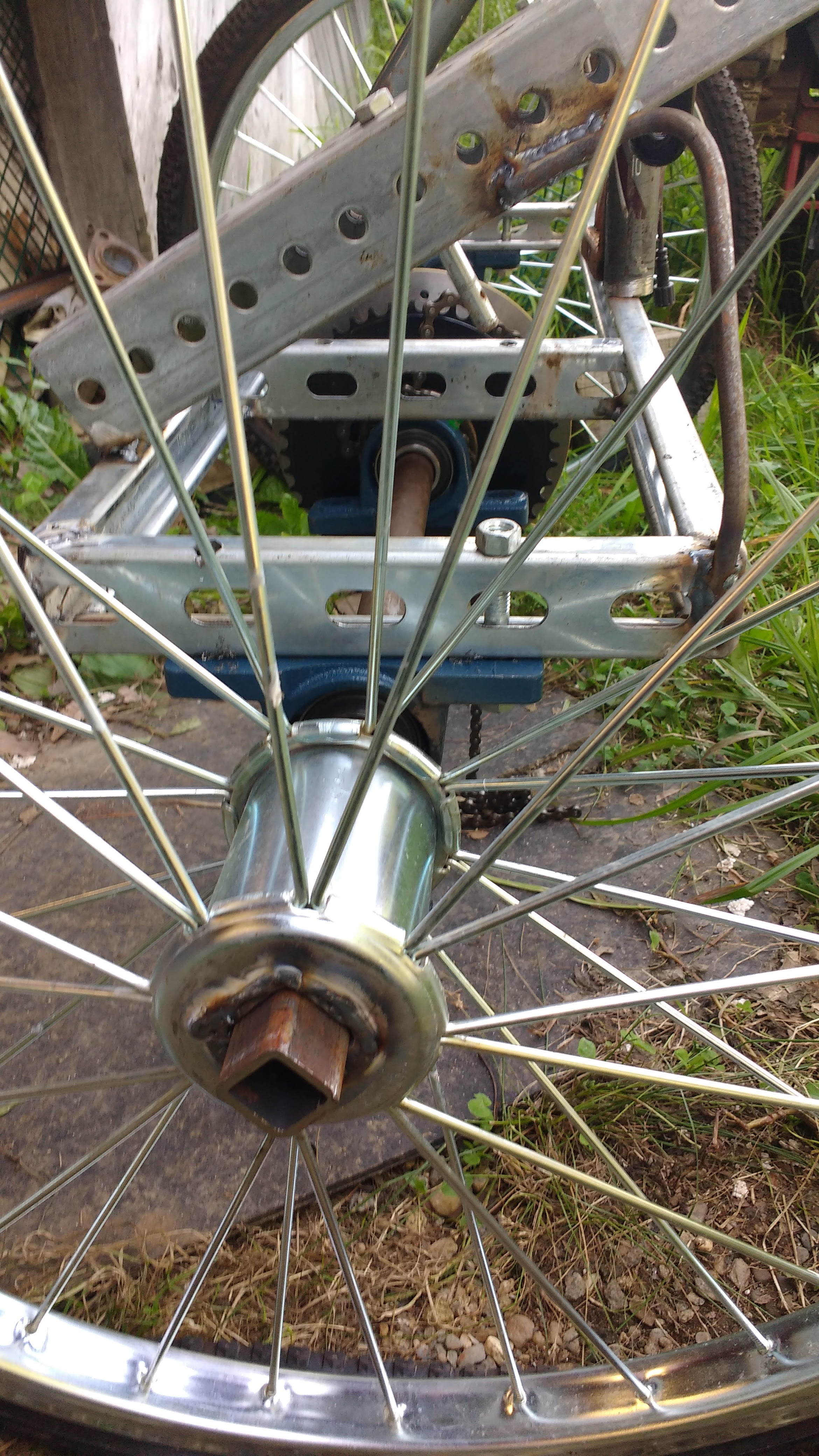
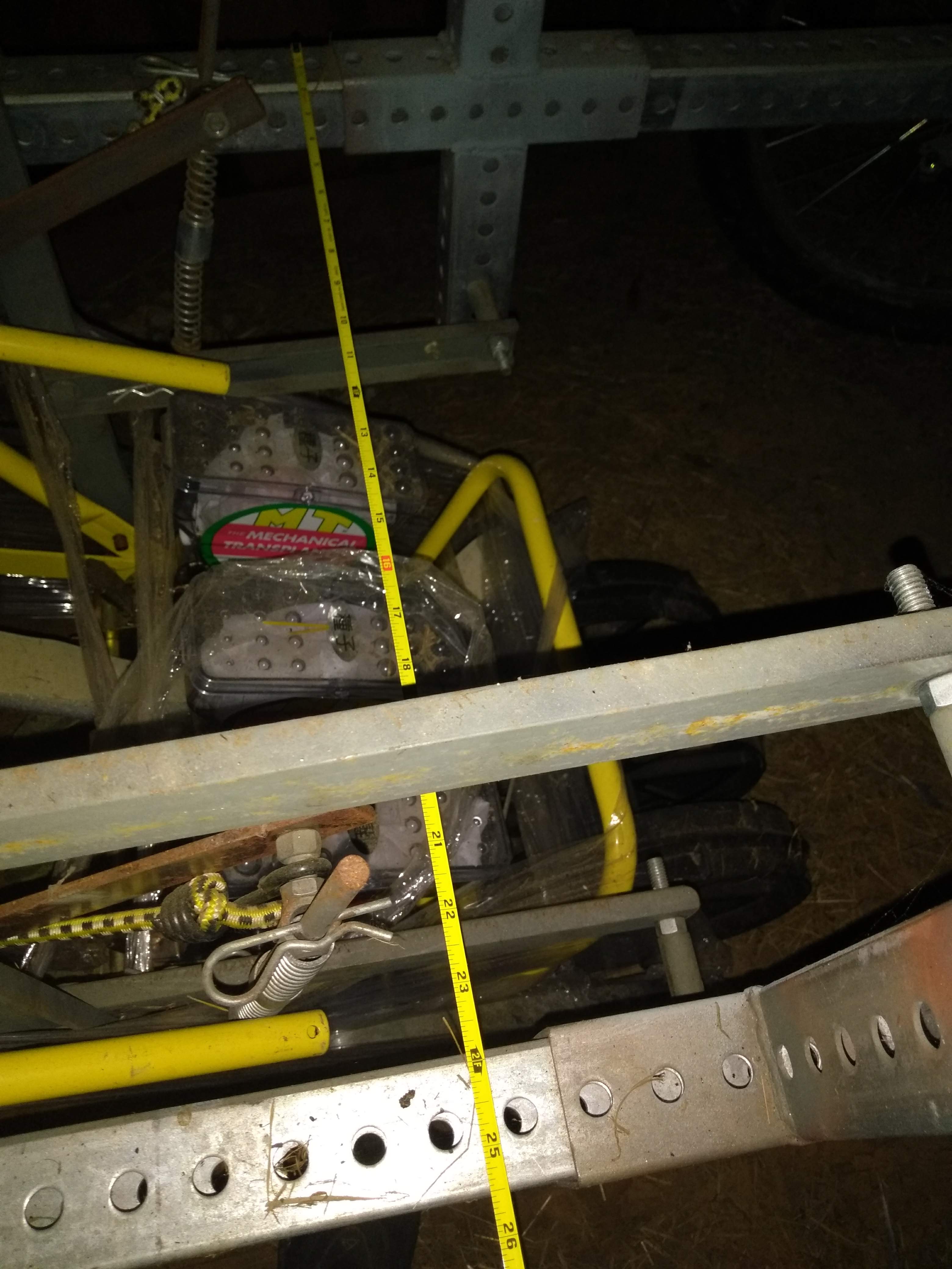
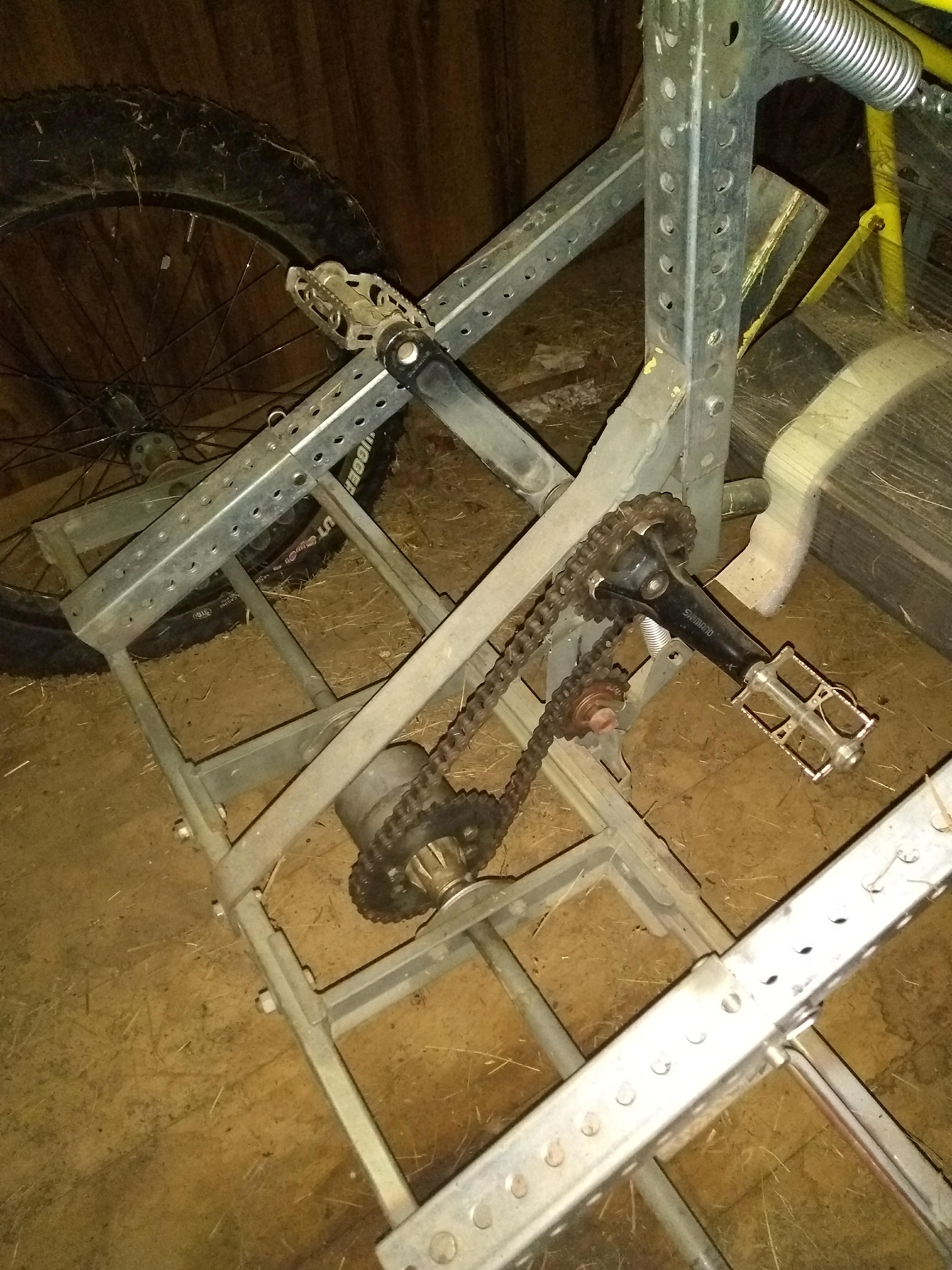
- a lawn tractor differential mounted in a unistrut rectangle for a rear end , with 3/4" round axles and 20” ATV tires;
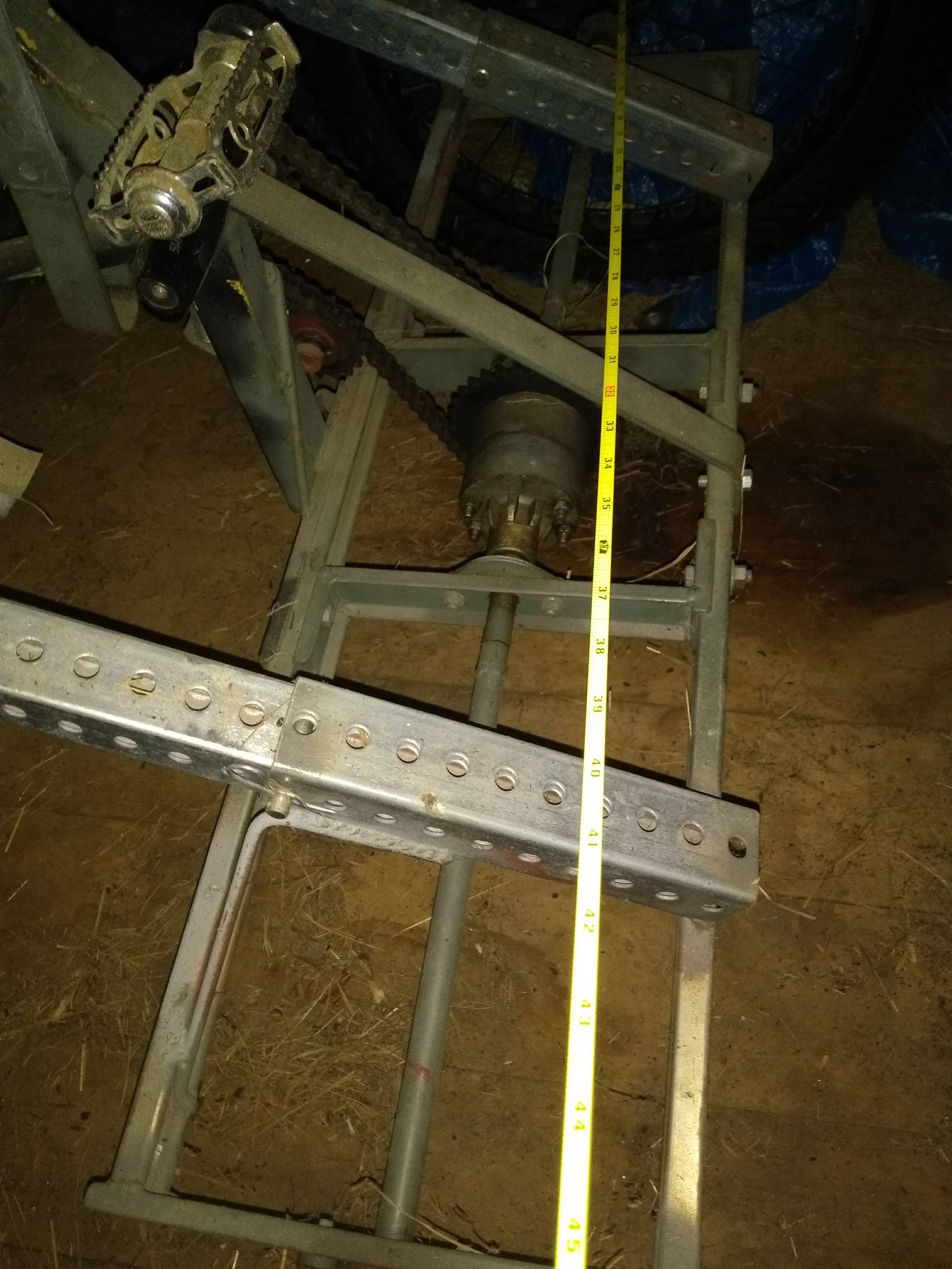
- a bike frame welded above the rear end with motorcycle sprocket and chain driving the differential (a springloaded idler tensions the chain);
- a belly mount lift to hold cultivators, seeders, etc.;
- a bike handlebar, separate from the bike frame and joined to the front end, steering the front wheels.
Bill of Materials from greentractorfarm Build (deleted google doc file)
Working Bill of Materials for Smith College Build (deleted google doc file)
Construction and How to Build
Step by step build document for earlier version before update to larger spoked rear wheels and spindle steering.
Annotated Picture of Parallel Lift Apparatus (deleted Google doc file)
Hand Drawing of Parallel Lift Apparatus (deleted Google doc file)
"
Culticycle Build Steps Part 1 from greentractorfarm (deleted Google doc file)
Culticycle Build Steps Part 2 from greentractorfarm (deleted Google doc file)
Working Chassis & Parallel Lift Build Steps from Smith College Build (deleted Google doc file)
CAD Documentation
Note: If you do not have CAD you can still view and measure from these files using edrawings. The file extension on GrabCAD is .EASM. Download the e-drawing viewer at http://www.edrawingsviewer.com/
Notes from Conversations about the above documentation with greentractorfarm:
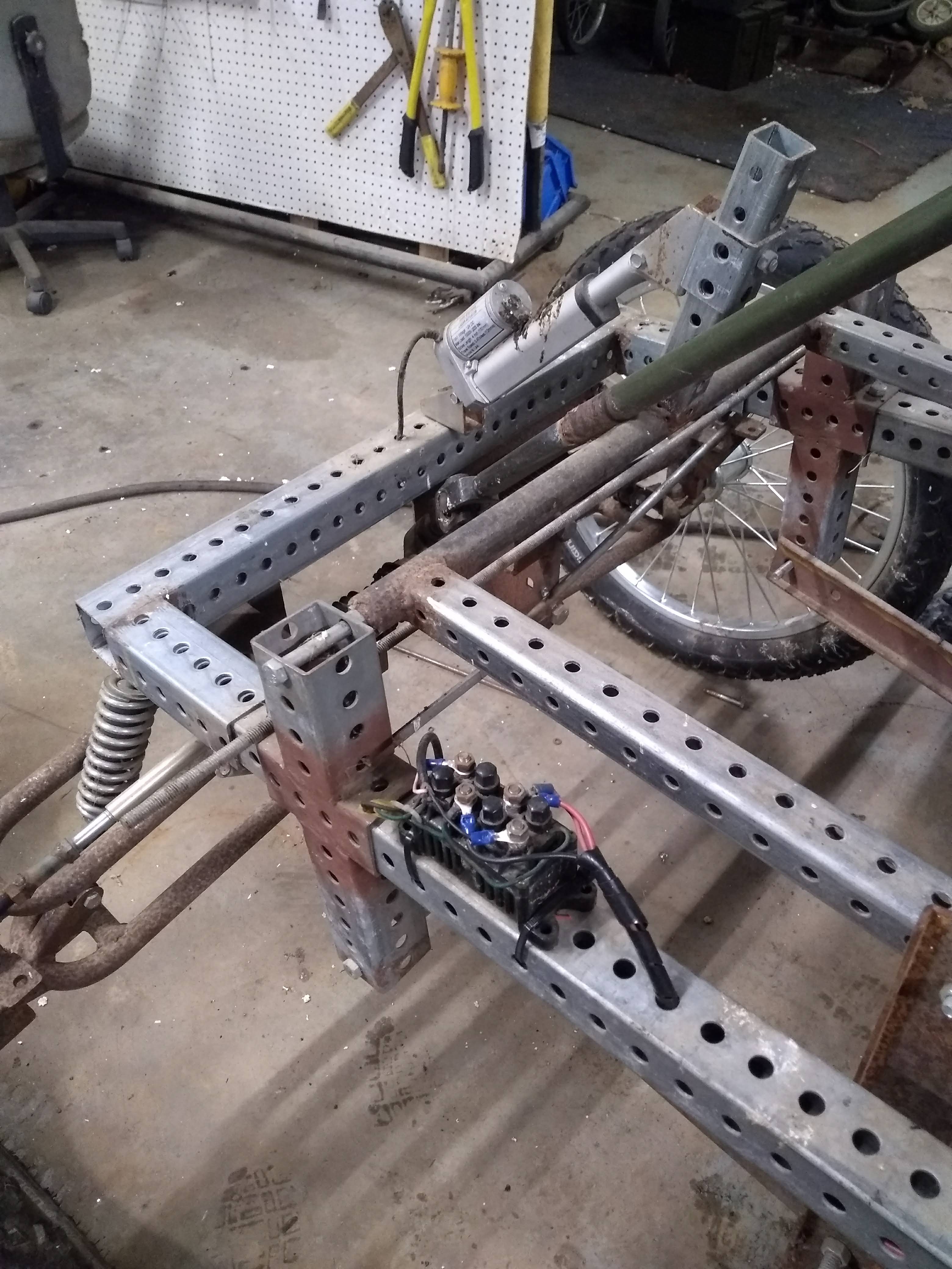
- thickness of the telespar 12 gauge or .1 inch
- diameter of the holes in the telespar 7/16"
- distance, on center, between the holes in the telespar 1"
- is this different for the 2" and 1.75" telespar no
- thickness of the channel used for the parallel lift arms 1/8" with gusseted sides; I was using 1/8" hot rolled but was talked out of it due to poor weld strength
-
the inside dimensions of the channel used for the parallel lift arms the inside is 15/16", due to the gussets; it's called 1/2" x 1 1/2 x 1/8" at the steel yard
-
Starting on Step 18 can you tell us the length of the perpendicular piece that connects the back of both parallel lift arms to the implement?
Those are the toolbar stanchions - they're welded to the tool itself, in other words each culticycle implement (tool) has these 2 vertical pieces. Definitely an open question as to how best to design it! They're in step 21 - they're 1/2 x 1 1/2 x 1/8 channel (in some pictures you'll see that I reused hot rolled channel from earlier tools). They are 18" long. -
We are thinking of fabricating the lift handle. What are the dimensions of that piece?
1 1/2 x 36 x 1/4, not including the 90 degree bend at the top if you go that way. -
In step 19, we are confused about the weld between the rockshaft and lift arms. is the 45 degree angle between the rockshaft and the lift handle. Would it be possible for you to send us a picture of the connection between the lift handle, schedule 40 pipe, and rockshaft arms?
The holes at the end of the rockshaft arms determine the vertical lift and you're trying to get the maximum out of them. Several things are in play: the quadrant gives you about 60 degrees of movement, so if the handle is vertical - as far forward as the driver can comfortably reach - and the rockshaft arms are at 8:00, then when the handle is pulled back to its maximum the rockshaft arms will be at 10:00. The vertical distance in this movement is about 9", that's the best I've done so far. It means a tool that works 1" deep can be lifted and transported 8" off the ground when you're turning around; not bad, but I'd like to get to 12". The joint of lift handle to sch.40 pipe is 90 degrees, and the arms are welded to the pipe at 8:00 with the handle clamped at 12:00. -
In step 19, "Drill a 3/8" hole 1" from the end of each to receive the pressure rods." Is this to the center of the hole?
Yes, good catch; and the longer these arms are, the more the vertical lift, within the limits of the other parts they're working with; maybe those 9" arms can get longer. -
What are the dimensions of the two vertical pieces that connect the quadrant to the chassis telestrut?
The one on the front is 10", on the rear 4", but those numbers are based on that particular quadrant. -
What is the thickness of the steel that the quadrant is fabricated from?
3/8" - but I'm having the new one based on the Allis Chalmers G cut from 1/4". -
What is the thickness of the two vertical pieces connect the quadrant?
In the picture, the front is channel and the rear is 1/4" bar steel. They can both be 1/4" x 1 1/2" bars. -
How imperative is it that the ATV tires are 25"? We have found two that are 24".
That's fine, the clearance difference is minimal. And if you look at that equation from the notechmagazine page, and you change 25 to 24, the result is π. -
What is the length of the springs for the pressure rods?
They're 3", wire size 3/32, inside bore 1/2", and on my bathroom scale it takes 40 pounds to compress 1".
Next Steps
1) Continued organization of wiki
2) Research and Concept Generation: Rear-End --> incorporation of a flywheel
3) Research and Concept Generation: Tool Modularity/Interchangeability with European Tool Carrier
4) CAD: Front-End, Rear-End, Lift-Handle, Seat
Related Tools
Low-cost Pedal Power Root Washer
Comments
Great Idea
Saw this at the New England Fruit and Vegetable Growers Conference in Manchester. I would love to connect UMaine Extension, the Biddeford, Maine Community Bicycle Center with a local small scale farmer to build a prototype.
prototype build
Hey Frank, I remember, great talking - there's a farmer near Rockland who might be interested - write me at greentractorfarm@gmail.com Tim
NEVF Conference
Hello there! I met you at the NEVF conference in NH a few months ago. You let me ride your AMAZING invention in the lobby. I would love to help you in any way I can. Please let me know what I can do! This is amazing.
Jess
hello green tractor farm!
Hello.
The gear ratio varies based