Functional Description
This livestock/cattle weigh scale uses pressure transducers to read the hydraulic fluid pressure in hydraulic rams under each corner of the weigh deck. Pressure is converted to force, and some basic statistical stuff is calculated and the resulting weight of the animal is wirelessly transmitted to the receiver which may be in sight outside the corral or in hand of a helper.
How to use the tool
Arrange a site for the scale supports so that the weigh deck is level and does not rock on the four hydraulic rams. You might want to pour small concrete pads for this purpose. Place the transmitter (wired to the pressure transducers via RCA connections) under the deck to protect it. Turn on transmitter and receiver and zero the deck (i.e. account for tare weight). Expect results to fluctuate just a few pounds based on the accuracy of your pressure transducers.
Materials and sourcing (main and non-obvious materials)
- Dwyer Series 628CR pressure transducers - four (one for each corner). Note that accuracy is stated in terms of "full scale" (FS). Example, a 500 psi transducer with 1% accuracy at FS has +/- 5 psi anywhere in that pressure range, so it is to your advantage to use the smallest pressure rating needed. This example used 500 psi which certainly works but is too conservative. The transducers are the largest single expense.
- Short body hydraulic ram from Harbor Freight, part no. 95979 This is sort of like a bottle jack. They are very short with a hydraulic piston that extends only 7/16 inch.
- moteino R4 This is an wireless arduino type board from http://www.lowpowerlab.com
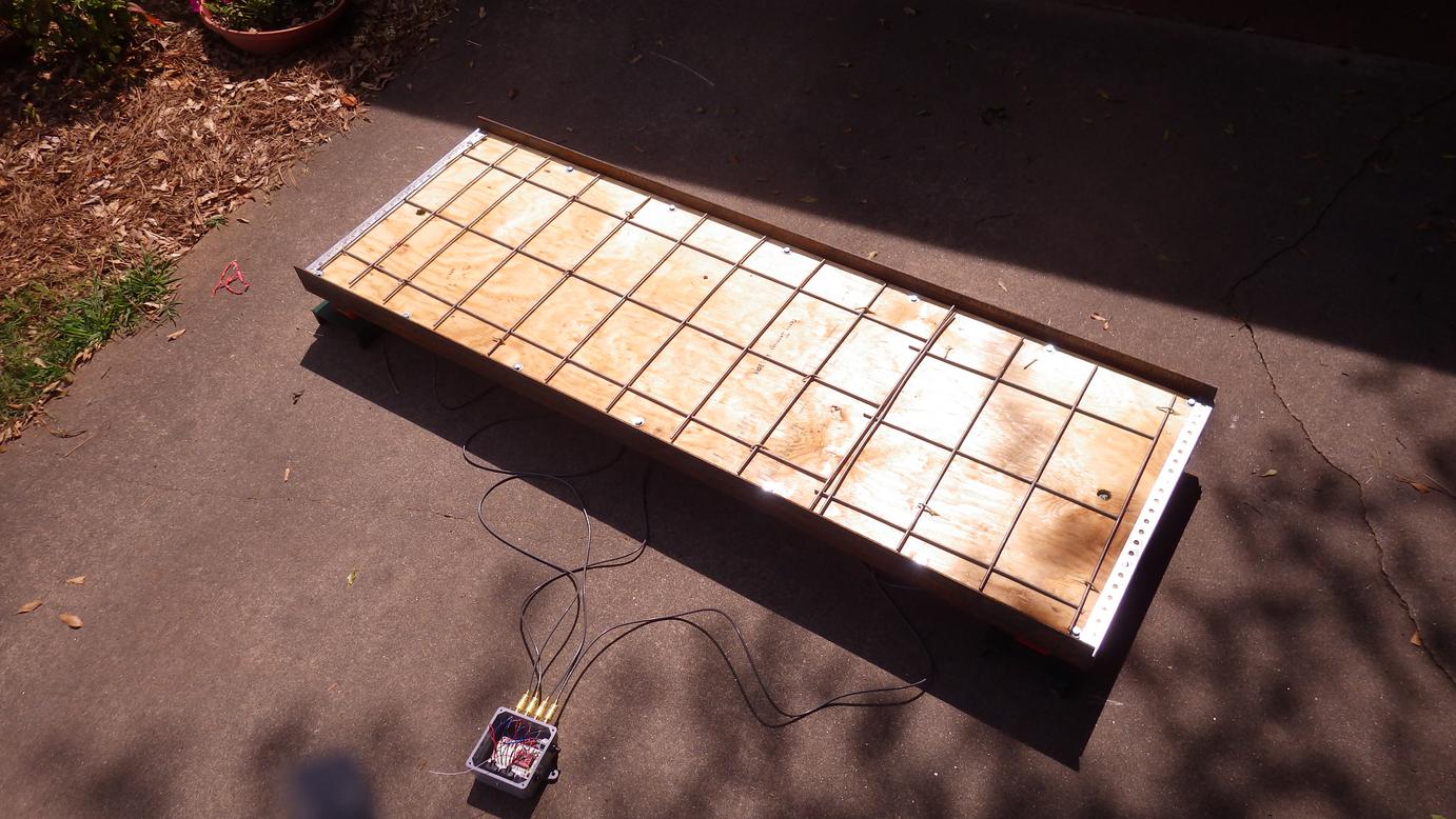
- the weigh deck consists of two layers of 21/32 in. (or thicker) 6 x 2 ft. plywood, anti-skid surface/material on top for hooves, and 3 x 2 x 3/16 in. angle bolted on sides for reinforcement
- two 2-ft. long sections of channel beam (as shown in images) or other suitable material to secure the hydraulic rams. Try a scrap steel yard.
- standoff screws to secure the printed circuit board (PCB) to the project box. So, select a PCB with pre-drilled standoff holes.
- small sheet of clear plastic (like for a picture frame) as a cover for the receiver box so you can see the display
- project box such as Cantex (Item #: 10029 | Model #: L5133709 at Lowes) "new work wall electrical box" or similar (e.g. Carlon) without any pre-made holes or outlets.
- RCA connectors
- tip: you will be looking for "panel mount" buttons, switches, RCA plugs, etc. to interface into the plastic project box
- See notes on the circuit diagrams for additional electronic parts and sources, etc.
Construction, how-to build
- Construct the deck as described and shown in the images.
- Remove the fittings that came with the hydraulic rams. Fully extend the ram piston using an air nozzle pressed into the hole. Then back off the piston 1/16 inch to allow for thermal expansion, etc. Fill each ram with hydraulic oil without any bubbles. A syringe with large gauge needle may be used. The recommended pressure transducers have the correct thread size to screw into the hydraulic rams. Use plumber's teflon tape.
- build the transmit and receiver boxes as shown in the images
- build the circuit boards as shown in the images
- program the moteinos in the transmit and receiver boxes: see post at https://lowpowerlab.com/forum/index.php/topic,782.0.html The code seems to be more properly formated there (Markdown syntax was not too clean here)
- The hardware and microcontroller programs should be considered opensource.
TRANSMITTER CODE
RECEIVER CODE