This material is based upon work supported by the National Institute of Food and Agriculture, U.S. Department of Agriculture, through the Northeast Sustainable Agriculture Research and Education program under subaward number SARE ONE-24-466 , Arduino For Small Farms.
Any opinions, findings, conclusions, or recommendations expressed in this publication are those of the author(s) and should not be construed to represent any official USDA or U.S. Government determination or policy.
GRAINBRAIN
An arduino based humidistat for drying grain in a plenum dryer
This material is based upon work supported by the National Institute of Food and Agriculture, U.S. Department of Agriculture, through the Northeast Sustainable Agriculture Research and Education program under subaward number SARE ONE-24-466 , Arduino For Small Farms.
Any opinions, findings, conclusions, or recommendations expressed in this publication are those of the author(s) and should not be construed to represent any official USDA or U.S. Government determination or policy.
In the Northeastern US, grain needs to be dried after it is harvested and threshed. A common way to dry the grain is with a “plenum dryer”, a box with a screened plenum at the bottom into which air is blown. The air blown into the plenum rises up through the grain and leaves the box at the top, taking moisture from the grain with it. The blower that forces air through the drying grain typically uses about 1000 watts of electricity per ton of grain, costing the farm ~$4 a day in electricity per ton of grain. Furthermore, the weather is not suitable for drying throughout the drying period (August), oscillating between high humidity (no drying possible), and low humidity (drying possible).
The Grainbrain helps the farm dry grain by monitoring the airflow into and out of the plenum dryer and automatically turning on and off the blower to maximize drying the grain and minimize electricity use. The Grainbrain uses a micro-controller (Arduino Nano), two temperature/humidity sensors, and computer code. It also has a data logger feature that logs the activity of the blower and the inlet and outlet airstreams. And, it has an input knob that allows the farmer to select the type of grain being dried, and to periodically input the moisture content (MC) of the grain as tested by the farmer during the drying process. The Grainbrain can be configured to control additional blowers if multiple bins of the same grain are being dried. The farmer can use the open-source feature of the computer code to adjust the various parameters of the program for custom drying projects.
Below there is a description of how the Grainbrain works, followed by an explanation of the electronics, and finally, the open-source code. Some familiarity with electronics, microprocessors, and computer code is required to understand the electronics and code. There are MANY good introductory youtube videos and online resources to help explain the basics.
WARNING: Please be careful with electricity. Using long extension cords around dusty barns is a fire hazard. Making electrical connections standing on wet ground is an electrocution risk. Make sure extension cord junctions are wrapped in electrical tape and are inside metal or plastic cans to stay dry and safe and away from flammable material.. Check the connections and the wires for heat build up and replace them if they get hot. Make sure the extension cords are grounded and properly sized for the load. Make sure the breaker protecting the extension cords is working and adequately sized. Do all work on wires with the power OFF. If there is doubt, then get help.
HOW THE GRAINBRAIN WORKS
The Grainbrain senses the temperature and humidity of the air entering and the air leaving the grain bin. Its computer then calculates the difference in absolute humidity (aH) of the two air streams– the “ drying differential”. If the drying differential is positive (more moisture in the outlet air than the inlet air), then drying is occurring (moisture is being removed from the grain). If the drying differential is negative, then wetting is occurring (moisture from the inlet air is being added to the grain). The Grainbrain turns off the blower (using a relay) if drying is not occurring. The Grainbrain turns the blower back on when the inlet air conditions change to make drying possible. The computer calculates when to turn the blower on using a variety of predictive equations (the “Equilibrium Moisture Content” equations) and the grain MC and grain type that the farmer has dialed into the Grainbrain. So a simple comparison of the air streams with “blower on” or “blower off” as the result would be all there is to it, except there are two complications to this simple scheme. First, even if the inlet air humidity is not low enough to dry the grain, the computer turns the blower on periodically to “ventilate” the grain. The grain needs periodic airflow to cool it and remove stuff that might cause germination or rot. Second, the grain needs more ventilation earlier in the drying process when the grain has more moisture in it, so the structure of the logic divides the drying into two epochs; the first when the grain MC is greater than 20% (more ventilation required), and the second when the grain MC is below 20% (less ventilation required). The farmer can easily change the code to adjust the parameters: The MC of the epochs, the various timers for the ventilation cycles, etc.
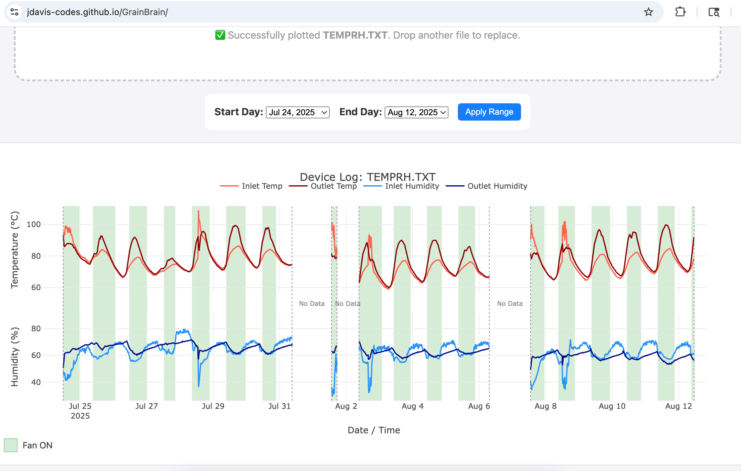
The Grainbrain displays the realtime data on a LCD. The Grainbrain also has an onboard time-and-date clock, along with a datalogger (micro SD card) that stores a file of the drying data. This file can be uploaded to a PC by the farmer and examined or shared. This data might help with analysis of drying, food safety, electricity use, and flavor.
HOW THE GRAINBRAIN’s ELECTRONICS WORK:
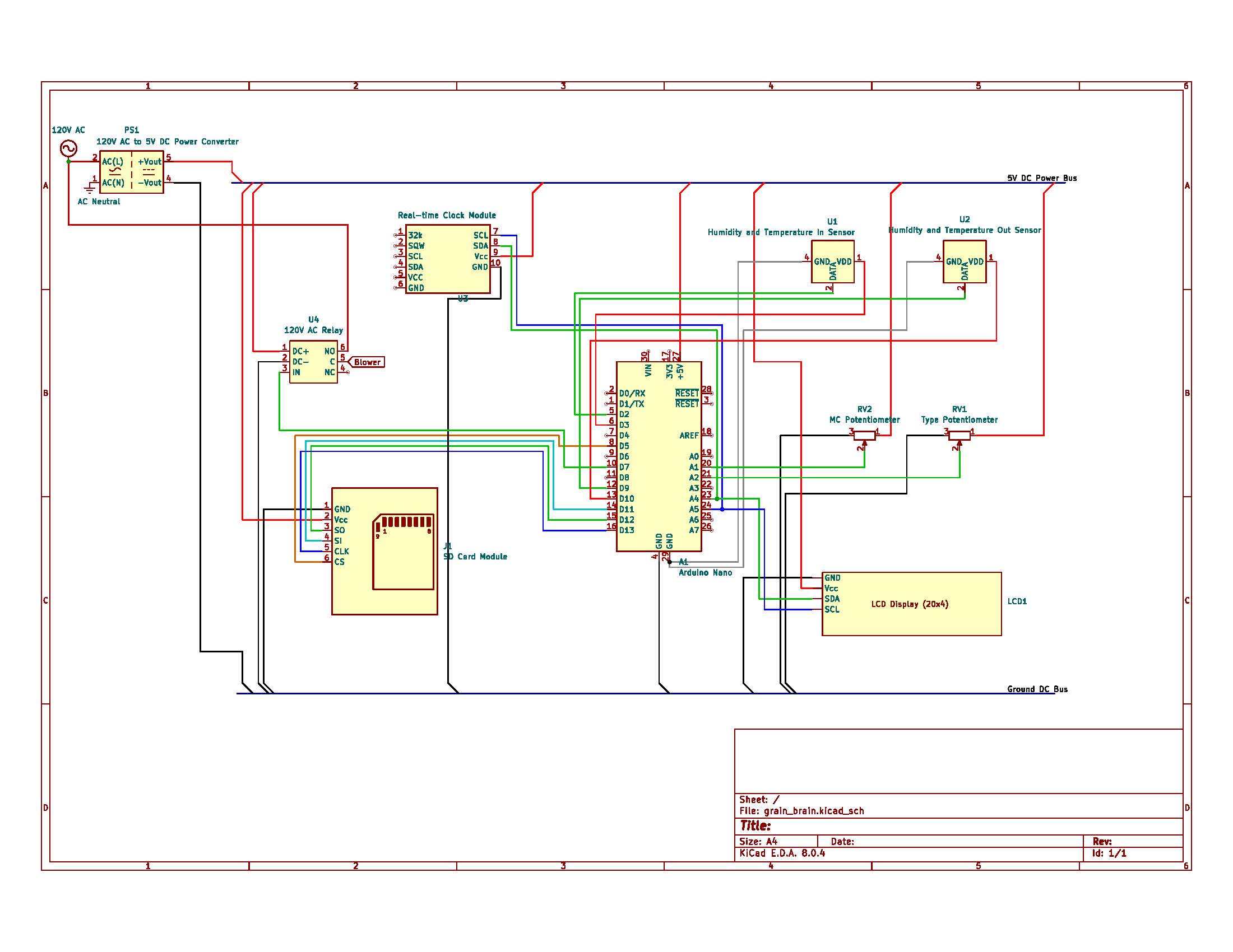
The Grainbrain is designed around an Arduino Nano. The Nano has inputs and outputs:
INPUTS:
*two DHT-22 temperature/humidity sensors
* a DS 3231 Clock module
*a 120VAC to 5VDC power supply to power the Arduino and sensors
*two dials (potentiometers) for inputting grain MC and grain type.
*
OUTPUTS:
*a 30 amp relay that controls the blower
*a 4x20 LCD (I2C communication protocol) that displays real-time data
*a micro SD card adapter reader/writer for logging data
*power to the DHT-22 sensors is configured as an output to allow automatic re-booting of sensors
The Grainbrain starts drying by turning on the blower. The blower runs for the Minimum Ventilation Time (either one hour or 15 minutes, depending on the grain MC). Then it begins checking the temperature and humidity of the air entering and leaving the grain bin. It uses a function to check the difference in absolute humidity (This function is thanks to Markus Weimar; visit his website: https://www.markusweimar.de/en/), the Drying Differential. If the drying differential is negative, the blower is turned off. The blower remains off until either one of the following conditions are met: 1. The blower is off for longer than the Maximum Off Time (6 hours or 12 hours, depending on the grain MC). 2.The calculated Equilibrium Moisture Content for the inlet air stream and grain type is a little less than the recorded grain MC (as measured and dialed in by the farmer). Then the blower is turned back on and the cycle starts again…
All the while, every 15 minutes the Arduino opens the datalogger file and records the date, time, and the various inlet and outlet data, as well as whether or not the blower is running. The SD card stores this data as a CSV file which can then be imported into a program (such as Excel) to graph the data. One example of a custom program is here: https://jdavis-codes.github.io/GrainBrain/ .
The Arduino Nano has additional digital pins available to add additional relays which can control blowers on additional grain bins, allowing the sensor data from a single grain bin to act as a proxy for drying grain in several grain bins. If several blowers are controlled from sensors on a single bin, please check electrical cables and connections carefully to avoid overloading wires.
The Grainbrain uses DHT-22 digital temperature and humidity sensors along with the code library “DHTStable.h” to connect the sensors to the Arduino. The sensors are used with two strategies for avoiding digital noise problems. First, the sensors are attached to the arduino using USB cables, with the Arduino end of the cables’ shield connected to ground. Second, the DHTStable library includes a code function that checks the sensors for digital errors. If the code detects an error in the sensor, then it “re-boots” the sensor automatically by turning it off and then back on again. To enable the automatic switching off and on of the sensors, the sensors get their power from an output pin on the arduino.
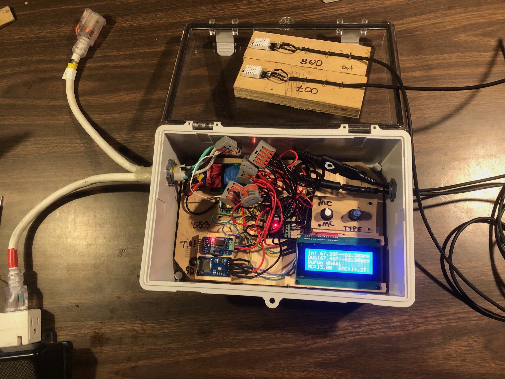
The AC (high voltage) side of the relay is covered with a clearly labeled piece of electrical tape so it is not inadvertently touched. The input to the relay (and the arduino’s power supply) is from the plug on a piece of extension cord. The output of the relay is to the receptacle end of an extension cord. This allows the blower to be plugged into the Grainbrain. In the event that the Grainbrain malfunctions or to test the blower, the farmer can simply “bypass” the grain brain by unplugging it and plugging the blower directly into the power source.
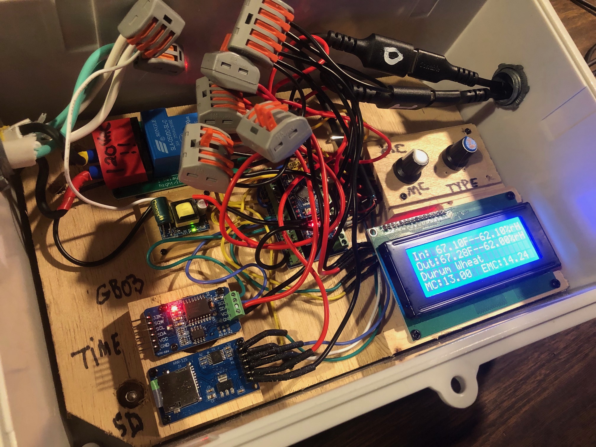
The 4 line LCD displays:
1. The Inlet air temperature (deg F) and relative humidity (%).
2. The outlet air temperature (deg F) and relative humidity (%).
Note that the Drying Differential is NOT displayed. This is because the units of the drying differential are confusing (units of pressure, hPa) and why trouble the farmer with a chemistry lesson?
3. The type of Grain. There are 7 possible types to select: Shelled corn, Cob corn, Oats, Durum Wheat, Red Wheat, Sunflower, Pinto beans, Black beans.
4. The measured MC (as measured by the farmer with grain MC tester), and the EMC (as calculated by the equations for each grain type and the inlet air temperature and humidity.
The Arduino Nano has a mini USB port into which a computer with Arduino IDE can be plugged, allowing the user to see data printed to the monitor in real time and to allow adjustments of the code.
The date/time module contains a CR2032 lithium rechargeable battery to hold the time and date when the arduino is powered off. The battery can hold the time and date for several weeks with the arduino off. However, periodically, the Grainbrain should be powered up even if not in use so that the battery can be automatically recharged. If the battery fails, then the time and date need to be reset with a piece of code available in the “examples” section of the Arduino IDE environment, called “DS3231_Serial_Easy.ino”. It will appear in the examples section after the DS3231 library (DS3231.h) is imported. If you are a novice at Arduino, you may need an arduinist or a twelve-year-old to help.
GRAINBRAIN BILL OF MATERIALS:
ARDUINO IDE CODE FOR GRAINBRAIN:
/*
*This sketch combines a arduino nano with a DS3231 clock module, two DHT-22 temperature/humidity sensors, and a micro-sd card module
*It also allows as input the type of grain being dried (as reference to equations that estimate the equilibrium Moisture Content for a given air temp and rH)
*And allows as input the latest measured MC as inputed with a potentiometer by the farmer
*The output is a relay that controls a blower on a plenum style grain drying bin.
*The program helps control and monitor grain drying
*Remember, to first set the day, time, and date on ds3231 use DS3231Serial_Easy_Lu or some other sketch that sets the day, time, and date
* check the pinout on your GrainBrain! GBO2 is different from GB01 and GB02
*/
//============================================================================BEGIN DECLARATIONS===========================================
#include <DS3231.h> //includes the library for using the DS3231 Time module
DS3231 rtc(SDA, SCL); //sets up the time module
#include <LiquidCrystal_I2C.h> //includes the library for using the 2x16 display with the built in I2C adapter
LiquidCrystal_I2C lcd(0x27,20,4); // I2C address 0x27, 20 column and 4 row
#include "DHTStable.h" //Include dhtStable library
DHTStable DHTinlet; //creates an instance of the DHTStable class for the inlet
DHTStable DHToutlet;//creates an instance of the DHTStable class for the outlet
#define DHT22inlet 2 //pin for dht inlet
#define inletPowerPin 3 //pin for dht inlet 5 volt power supply
#define DHT22outlet 9 //pin for dht outlet
#define outletPowerPin 10 //pin for dht outlet 5 volt power supply
float inletTemp; //these 4 variables will store the temperatures (in Celcius!) and humidities (%rH) from the sensors
float inletHum;
float outletTemp;
float outletHum;
#include <SPI.h> //library for Serial Peripheral Interface communication
#include <SD.h> //library for microSD card
const int chipSelect = 5;// sets pin 5 for CS on the microSD module pinout
File myFile; //creates a file for the micro SD card
int potPin = A1; //declare the potentiometer pin A1
int potVolt = 0; // will be the voltage of the dimmer (0-5 volts), read as a integer from 0-1023
float grainMCx2 = 0; //a variable for the entering of the grain moisture content times two to avoid the integer math problem of the mapping function
float grainMC = 0; //a varialble for entering the grain moisture content with resolution of 0.5%
int grainTypePotPin = A2;//potentiometer to select grain type
int grainTypePotVolt = 0;//variable that potentiometer voltage is read into
const int numberOfGrains = 8;
char *grainType[numberOfGrains] = {"Shelled Corn", "Cob Corn", "Oats","Durum Wheat", "Red Wheat", "Sunflower", "Pinto Beans", "Black Beans"}; //this string array holds the different types of grain
int i = 0; //i is the variable that stores the grain type, integer from 0 to (number of grains)
//variables for timer on for the microSD card write function
unsigned long writeInterval = 5000;
unsigned long runTime;
unsigned long startTime1 = 0;
//variables for the timer on the function to read the sensors
unsigned long readInterval = 3000;
unsigned long readTime ;
unsigned long startTime2 = 0;
//variables used for the function that checks for the difference in water vapor pressure
float inletP; //units are pressure: hectoPascals hPa
float outletP; //units are pressure: hectoPascals hPa
float AHDifference; //difference in pressure hPa
float inletSatP; //pressure in hPa
float outletSatP; //pressure in hPa
float ahThreshold; //the threshold difference in humidity (as measured by h2o vapor pressure) at which blower shuts off
// global variables used in grain EMC calculator
float mcEq;
//global variables used in logicAndControl subroutine
int blowerOn;
unsigned long blowerTimer;
const int relayPin = 7;
unsigned long minVentilationTime; //5 seconds for testing reset to 4 hours
unsigned long maxOffTime; //20 seconds for testing reset to 4 hours
//============================================================END DECLARATIONS=======================================================
//=============================================================BEGIN SETUP==========================================================
void setup() {
Serial.begin(9600);
// wait for Serial Monitor to connect. Needed for native USB port boards only:
while (!Serial);
Serial.print(F("Initializing SD card..."));
if (!SD.begin(chipSelect)) {
Serial.println(F("initialization failed. Things to check:"));
Serial.println(F("1. is a card inserted?"));
Serial.println(F("2. is your wiring correct?"));
Serial.println(F("3. did you change the chipSelect pin to match your shield or module?"));
Serial.println(F("Note: press reset button on the board and reopen this Serial Monitor after fixing your issue!"));
while (true);
}
Serial.println(F("initialization done."));
delay(20);
rtc.begin(); // Initialize the DS3231 realtimeclock object
lcd.init(); // Initialize the lcd object, clear it, turn on the backlight, set the cursor (?)
lcd.clear();
lcd.backlight();
lcd.setCursor(0,0);
pinMode (potPin, INPUT); //turn on potPin as input this will input the grain MC
pinMode (grainTypePotPin, INPUT);//turn on grainType potentiomenter as input
pinMode (inletPowerPin, OUTPUT); //turn on inlet power pin as output
pinMode(outletPowerPin, OUTPUT); //turn on outlet power pin as output
digitalWrite (inletPowerPin, HIGH); //turn on inlet power pin so sensor is on
digitalWrite (outletPowerPin, HIGH);//turn on outlet power pin so sensor is on
//initialize the logicandControl variables
pinMode (relayPin, OUTPUT);
blowerTimer = millis();
digitalWrite (relayPin, HIGH);//turn on blower
blowerOn = 1;//set blower state variable to true
}
//====================================================================END SETUP============================================================
//=============================================================================MAIN LOOP================================================================
void loop() {
readInterval = (1000 * 3); //the read interval in milliseconds for the readSensors function
readTime = (millis() - startTime2);
if (readTime > readInterval){
readSensors(); //gets temperature and humidity readings from two sensors
startTime2 = millis(); //resets the timer
}
readGrainType(); //reads potentiometer to detect selected grain type
readGrainMC(); //farmer tests grian and inputs moisture content using potentiometer
displayLCD(); //displays things on LCD (4x20)
humidityDifference(); //calculates the differential of H20 vapor pressure. A positive difference indicates drying
if(i >=0 && i <= 4){ //for the first 5 grain types use the following equation
calculateEMCOswin (); //calculates the Equilibrium Moisture Content given the grain type, inlet air temp and rH using the Modified Oswin equation
}
if (i >=5 && i<=7){ //for the last 3 grain types use the following equation
calculateEMCHalsey (); //calculates the EMC given the grain type, inlet air temp, and rH using the Modified Halsey Equation
}
logicAndControl();//controls the relay based on the conditions
printToMonitor(); //prints data to Serial Monitor if a computer is connected with an active serial monitor
//writeInterval = (1000 *5); //writes every 5 seconds
writeInterval = 900000; //writes every 15 minutes
runTime = (millis() - startTime1);
if (runTime > writeInterval){
writeToSD(); //writes data to microSD card
startTime1 = millis();
}
delay(100);
}
//==========================================================END MAIN LOOP=================================================================
//===========================================================BEGIN SUBROUTINES==============================================================
void readSensors(void) {
//===============================================SUBROUTINE TO READ TEMPERATURE AND HUMIDITY WITH DHT-22=============================================
int chkinlet = DHTinlet.read22(DHT22inlet); //calls a function to check the sensor for read errors--ok=0;errors are 1,2,etc
int chkoutlet = DHToutlet.read22(DHT22outlet);//calls a function to check the sensor for read errors.
if (chkinlet != 0){//if the read error function returns other-than-zero, there's a problem with the sensor and it prints the error and gets rebooted
printDHTError(chkinlet);
rebootDHT22 (inletPowerPin);
delay (10);
}
if (chkoutlet != 0){
printDHTError(chkoutlet);
rebootDHT22 (outletPowerPin);
delay (10);
}
inletHum = DHTinlet.getHumidity();
inletTemp = DHTinlet.getTemperature();//Celcius!
outletHum = DHToutlet.getHumidity();
outletTemp = DHToutlet.getTemperature();//Celcius!
// DISPLAY DATA FOR TESTING
/* Serial.print(F("DHT22 Inlet, \t"));
printDHTError(chkinlet);
Serial.print(inletHum);
Serial.print(F(",\t"));
Serial.print(inletTemp);
Serial.print(F(",\t"));
Serial.println();
Serial.print(F("DHT22 Outlet, \t"));
printDHTError(chkoutlet);
Serial.print(outletHum);
Serial.print(F(",\t"));
Serial.print(outletTemp);
Serial.print(F(",\t"));
Serial.println();
*/
//=================================================END TEMPERATURE AND HUMIDITY SUBROUTINE===========================================================
}
//==================================================SUBROUTINE TO READ POTENTIOMETER FOR SELECTED GRAIN TYPE====================================
void readGrainType(void){
grainTypePotVolt = analogRead (grainTypePotPin);// a simple analog read of the potentiometer which gets an integer between 0-1023
i = map (grainTypePotVolt,0,1023,0,numberOfGrains);//maps the potentiometer read on to the number of possible grains to select
}
//===================================================END READ GRAIN TYPE SUBROUTINE=============================================================
void readGrainMC(void){
// ================================================SUBROUTINE TO READ POTENTIOMETER FOR LATEST GRAIN MC INPUT===============================================
potVolt = analogRead (potPin); //read the potentiometer voltage into the variable potVolt (0-1023), more resistance means lower voltage
grainMCx2 = map(potVolt,1023,0,0,60); //creates the grainMC variable from the pot input allows grianMC from 0%-30%
grainMC = grainMCx2/2; // to get the resolution to 0.5% it's necessary to change the integer (0-60) to a decimal (0-30 in increments of 0.5)
// ========================================================END READ POTENTIOMETER SUBROUTINE===================================================
}
void displayLCD(){
//==================================================SUBROUTINE TO DISPLAY INFO ON THE LCD SCREEN======================================================
// Now display the temperature and humidity on the lcd, along with the selected grain type and the inputted MC and calculated EMC
lcd.setCursor(0,0);
lcd.print(F("In: "));
lcd.print((inletTemp * 9.0) / 5.0 + 32.0);
lcd.print(F("F--"));
lcd.print(inletHum);
lcd.print (F("%rH"));
lcd.setCursor(0,1);
lcd.print(F("Out:"));
lcd.print((outletTemp * 9.0) / 5.0 +32);
lcd.print(F("F--"));
lcd.print(outletHum);
lcd.print(F("%rH"));
lcd.setCursor(0,2);
lcd.print(" ");//erases previous characters from previous selected grain
lcd.setCursor(0,2);
lcd.print(grainType[i]);
lcd.setCursor(0,3);
lcd.print(F("MC:"));
lcd.print(grainMC);
lcd.print(F(" "));
lcd.print(F("EMC:"));
lcd.print(mcEq);
delay(20);
//===================================================END LCD SUBROUTINE================================================================================
}
void printToMonitor(void){
//=====================================================SUBROUTINE TO PRINT TO SERIAL MONITOR===========================================================
// Send date to serial monitor
Serial.print(rtc.getDateStr());
Serial.print(F(" -- "));
// Send time to serial monitor
Serial.println(rtc.getTimeStr());
// Printing the temperature and humidity on the serial monitor
/*
Serial.print(F("Inlet Temperature F: "));
Serial.println(((inletTemp * 9.0) / 5.0 + 32.0));
Serial.print(F("Inlet Humidity: "));
Serial.println(inletHum);
Serial.print(F("Outlet Temperature F: "));
Serial.println(((outletTemp * 9.0) / 5.0 + 32.0));
Serial.print(F("Outlet Humidity: "));
Serial.println(outletHum);
*/
//Serial.print(F("moisture content: "));
//Serial.println(grainMC);
Serial.println(grainType[i]);
Serial.print(F("humidity pressure difference: "));
Serial.println(AHDifference);
//Serial.print(F("Grain EMC: "));
//Serial.println(mcEq);
if (blowerOn==1) {
Serial.println(F("blower ON"));
}
else {
Serial.println(F("blower OFF"));
}
Serial.print (F("min ventilation time: "));
Serial.println(minVentilationTime);
Serial.print (F("max off time: "));
Serial.println(maxOffTime);
Serial.print(F("blower timer = "));
Serial.println(millis() - blowerTimer);
delay(50);
//=======================================================END SERIAL MONITOR SUBROUTINE===============================================
}
void writeToSD(void){
//=======================================================SUBROUTINE TO WRITE DATA TO MICROSD CARD=====================================
//open file on micro-sd card and write data to file
// open the file. note that only one file can be open at a time,
// so you have to close this one before opening another.
myFile = SD.open("TempRH.txt", FILE_WRITE); //tempRH.txt is the file name, FILE_WRITE tells the computer that this is a write operation
// if the file opened okay, write to it:
if (myFile) {
Serial.print(F("Writing to TempRH.txt..."));
//with the file open, write the date, time, temp, and humidity separated by commas
myFile.print(rtc.getDateStr());
myFile.print(F(","));
myFile.print(rtc.getTimeStr());
myFile.print(F(","));
myFile.print((inletTemp * 9.0) / 5.0 + 32.0);
myFile.print(F(","));
myFile.print(inletHum);
myFile.print(F(","));
myFile.print((outletTemp * 9.0) / 5.0 + 32.0);
myFile.print(F(","));
myFile.print(outletHum);
myFile.print(F(","));
myFile.println(blowerOn);
// close the file:
myFile.close();
Serial.println(F("done."));
} else {
// if the file didn't open, print an error:
Serial.println(F("error opening test.txt"));
}
delay(100);
//=======================================================END MICRO SD CARD SUBROUTINE=======================================================
}
//==========================================================BEGIN SUBROUTINE FOR WATER VAPOR PRESSURE DIFFERENCE================================
//This subroutine is thanks to Markus Weimar; visit his website: https://www.markusweimar.de/en/
void humidityDifference(){
inletSatP = 6.11 * exp((17.62 * inletTemp) / (243.12 + inletTemp)); //use the Magnus equation to get the inlet Saturation pressure in hPa
outletSatP = 6.11 * exp((17.62 * outletTemp) / (243.12 + outletTemp)); //use the Magnus equation to get the outlet Saturation pressure in hPa
inletP = (inletHum/100) * inletSatP; //take the ratio of the inlet RH to saturation to get the inlet vapor pressure
outletP = (outletHum/100) * outletSatP; //take the ratio of the inlet RH to saturation to get the outlet vapor pressure
AHDifference = outletP - inletP; // subtract the inlet from the outlet; a positive number indicates drying
}
//============================================================END SUBROUTINE FOR WATER VAPOR PRESSURE DIFFERENCE=================================
//=============================================================BEGIN SUBROUTINE TO CALCULATE GRAIN MC OSWIN EQUATION==================================================
void calculateEMCOswin (){
//this is the modified Oswin Equation
float constants[8][3] = {{15.303,-0.10184,3.0358}, {15.306,-0.084674,2.9764}, {12.412, -0.060707, 2.9397},
{13.101, -0.052626, 2.9987}, {15.868, -0.10378, 3.0842}, {3.2945,-0.0143,1.8641}, {4.4181,-0.011875,1.7571}, {5.2003, -0.022685, 1.9856}};
//the first 5 are the ABC constants for the Modified Oswin Equation, and the last 3 are the Modified Halsey Equation constants
//the Modified Oswin Equation covers the following grains: "Shelled Corn", "Cob Corn", "Oats","Durum Wheat", "Red Wheat"
//the Modified Halsey Equatin covers the following grains: "Sunflower", "Pinto Beans", "Black Beans"
float a = constants[i][0]; //these are the three constants for whatever grain type is selected
float b = constants[i][1];
float c = constants[i][2];
float h = inletHum/100; //the humidity in the equation is expressed as a decimal proportion
float denominator = pow(((1/h)-1), 1/c); //the denominator is ((1/h)-1)^(1/c)
mcEq = (a+ (b*inletTemp))/denominator;
}
//=================================================================END SUBROUTINE TO CALCULATE GRAIN EMC=============================================
//=============================================================BEGIN SUBROUTINE TO CALCULATE GRAIN MC HALSEY EQUATION==================================================
void calculateEMCHalsey (){
//this is the modified Halsey Equation
float constants[8][3] = {{15.303,-0.10184,3.0358}, {15.306,-0.084674,2.9764}, {12.412, -0.060707, 2.9397},
{13.101, -0.052626, 2.9987}, {15.868, -0.10378, 3.0842}, {3.2945,-0.0143,1.8641}, {4.4181,-0.011875,1.7571}, {5.2003, -0.022685, 1.9856}, };
//the first 5 are the ABC constants for the Modified Oswin Equation, and the last three are the ABC constants for the Modified Halsey Equation
//the Modified Oswin Equation covers the following grains: "Shelled Corn", "Cob Corn", "Oats","Durum Wheat", "Red Wheat"
//the Modified Halsey Equatin covers the following grains: "Sunflower", "Pinto Beans", "Black Beans"
float a = constants[i][0]; //these are the three constants for whatever grain type is selected
float b = constants[i][1];
float c = constants[i][2];
float h = inletHum/100; //the humidity in the equation is expressed as a decimal proportion
double denominator = log(h); //the Modified Halsey equation has the ln(rH) in the denominator. it's a double because that's what log() asks for
float numerator = -exp (a + (b * inletTemp)); //this is the numerator expression for the modified Halsey equation
mcEq = pow( (numerator /denominator), 1/c); //the MC is the Cth root of the numerator divided by the denominator
}
//=================================================================END SUBROUTINE TO CALCULATE GRAIN EMC=============================================
//==============================================================BEGIN LOGIC AND CONTROL SUBROUTINE===================================================
void logicAndControl(){
if (grainMC >= 20.0){ //this checks if the grain is still moist, and...
minVentilationTime = 3600000; //lengthens the ventilation time (1 hour) and...
maxOffTime = 21600000; //shortens the time (6 hours) the blower is off when it is turned off
ahThreshold = -0.25; //when the grain is still pretty wet this larger difference keeps the blower running longer
}
else if (grainMC < 20.0){ //this checks if the grain is drier, and...
minVentilationTime = 900000; //shortens the ventilation time (to 15 minutes) and...
maxOffTime = 43200000; //lengthens the time the blower is off (to 12 hours)
ahThreshold = 0.0; // if the grain is dryer then allow the blower to turn off at the first hint of too humid conditions
}
if (blowerOn == 1){ //if the blower is running
if ((millis() - blowerTimer) > (minVentilationTime)){ //and it has run for the minimum ventilation time
if (AHDifference < ahThreshold){ //and the difference in partial pressures indicates wetting of the grain instead of drying
digitalWrite (relayPin, LOW); //then turn off the blower
blowerOn = 0; //change the blower state variable to off (zero)
blowerTimer = millis(); //reset the state of on or off timer for the blower
}
}
}
if (blowerOn == 0){ //if the blower is off
if (((millis() - blowerTimer) > maxOffTime) | (mcEq + 0.5 < grainMC)){
digitalWrite (relayPin, HIGH);
blowerOn = 1;
blowerTimer = millis();
}
}
}
//====================================================================END LOGIC AND CONTROL SUBROUTINE================================================
//=======================================================BEGIN SUBROUTINE TO CHECK DHT22 SENSOR ERROR=================================================
void printDHTError(int chk){
switch (chk)
{
case DHTLIB_OK:
//counter.ok++;
Serial.print("DHT22 SENSOR OK,\t");
break;
case DHTLIB_ERROR_CHECKSUM:
//counter.crc_error++;
Serial.print("DHT22 Checksum error,\t");
break;
case DHTLIB_ERROR_TIMEOUT:
//counter.time_out++;
Serial.print("DHT22 Time out error,\t");
break;
default:
///counter.unknown++;
Serial.print("DHT22 Unknown error,\t");
break;
}
}
//=======================================================END SUBROUTINE TO CHECK DHT22 SENSOR ERROR======================
//=======================================================BEGIN SUBROUTINE TO RE-BOOT DHT22 IN CASE OF ERROR============================
void rebootDHT22( int powerPin){ //accepts as input the powerpin of the sensor that got an error code
digitalWrite (powerPin, LOW); //turns off the power to that sensor
delay (50); //waits 50 milliseconds
digitalWrite (powerPin, HIGH); //turns the sensor's power back on
}
//========================================================END SUBROUTINE TO RE-BOOT DHT22 SENSOR ======================================
// END OF PROGRAM
ACKNOWLEDGEMENTS :
This material is based upon work supported by the National Institute of Food and Agriculture, U.S. Department of Agriculture, through the Northeast Sustainable Agriculture Research and Education program under subaward number SARE ONE-24-466 , Arduino For Small Farms.
Any opinions, findings, conclusions, or recommendations expressed in this publication are those of the author(s) and should not be construed to represent any official USDA or U.S. Government determination or policy.
Several people made significant contributions to this project. Noah Kellerman originally complained about grain drying, sparking work on a solution. He continues to test and critique prototypes (and he continues, against all odds, to grow grain!). Meagan Rittmanic threw me into the micro-controller pond and watched me flounder. Anni Schmidt wrote the original code, and participated in testing the original prototype. James Davis consulted on code and “peripherals”. And NE SARE provided the grant that allowed me to build, test, and validate the prototypes on real grain, which led to many improvements in both design, electronics, and code.