

Hi Hackers, I am new to this community and relatively new to farming itself. This is our second year of production and its already time to start planting onions up here in Quebec. We have decided to start the Alliums indoors for the first month and move them out to the greenhouse at the beginning of April. We didn't feel that it was worth it to heat the greenhouse yet, when overnight temps are still regularly below 0. So as we did last year, we have moved a few greenhouse tables inside and set up 400 watt sodium halide lights above them. This worked pretty well last year. But this year I want to build an Arduino based timer to control the light cycles. I am already familiar with the Arduino's and have posted a tool wiki, on my basic setup of a "Temperature Data Logger".
The reason I think the Arduino is really good for this project is because I can control multiple circuits with one controller. This year we are using 4 lights. Plugged into a 15 amp cirucit, and 120 volts, that means we can have 1800 watts safely on that circuit. That technically would power all 4 lights (4 X 400= 1600). However there is some other household stuff on those circuits so I divided them up onto 2 circuits in the house to be safe. I will use a couple of powerswitch tails 2 to control the 2 circuits. The wiring and code looks pretty straight forward for this project, and I will try and document it as I go.
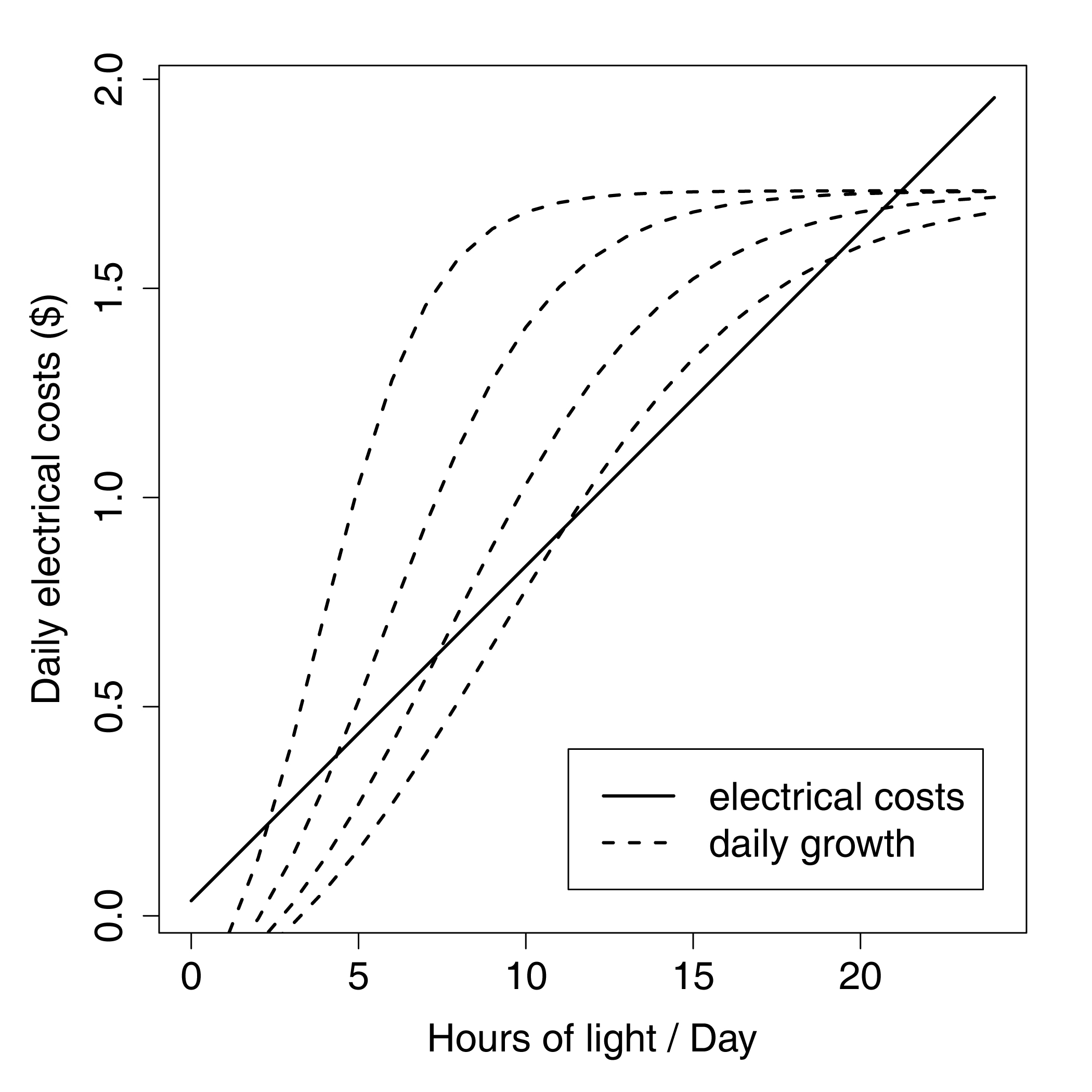
The question is what is the best light cycle to use? I have 1600 watts of light over about 90 sqft. or about 17.8 watts per sqft. I am curious what other are doing or would do for a light cycle. I have attached a graph showing the hypothetical differences. Up here in Quebec, it doesn't make too big of a difference as we only pay about $0.05/kilowatt hour. Cheap. But still curious as to what would be best. I haven't searched the internet much for an answer yet, I am sure somebody must have asked these questions before.
Jenna
I moved things forward on the onion seedling room project. It took a while but I finally got an arduino sketch that works to control the powerswitch tails. Also after some net searching it seems 14-16 hours is a good amount of time to leave the lights on. I connected the 'in+' of the powerswitch tails to digital pins 8 and 9 and the 'in-' to ground. The stripped down sketch for the timer looks like this:
     // Program .....: RTC_Relay
     // Author ......: Jenna Jacobs (adapted from Joe Pitz, Objetek Systems, objetek@gmail.com)
     // Copyright ...: Creative Commons, CC BY-SA
     // Description .: Turn on and off two power switch tail 2s
     // Date Created.: 3/20/2013
     // Usage and dependencies:
     //
     // Variables are used to set start time and end time.
     // Times are based on 24 hour clock, i.e.:
     // 1:00 pm = 13:00 and Midnight is 00:00
     //
     // Start time must be less than end time and both times must fall within the
     // same 24 hour period.
     //
     // Code uses RTCLIB, a branch provided from:
     // https://github.com/adafruit/RTClib
     //
#include <Wire.h> #include "RTClib.h" RTC_DS1307 RTC; // Setup Start and End TImes // This is where you define your start hour and start minute times unsigned int StartHr = 7; unsigned int StartMin = 30; unsigned int EndHr = 22; unsigned int EndMin = 30; // This is where we create a combined time in Day minutes (the number // of minutes since the start of the day) unsigned int DayMin = 0; unsigned int StartDayMin = (StartHr*60) + StartMin; unsigned int EndDayMin = (EndHr*60) + EndMin; // ledPin used for debug using Arduino on board LED. int ledPin = 13; // Pins used to control powerswitch tails (pst) int pstPin1 = 8; // Set our LED pin int pstPin2 = 9; // Set our LED pin void setup () { Serial.begin(9600); Wire.begin(); RTC.begin(); pinMode(pstPin1, OUTPUT); pinMode(pstPin2, OUTPUT); RTC.adjust(DateTime(__DATE__, __TIME__)); if (! RTC.isrunning()) { Serial.println("RTC is NOT running!"); // following line sets the RTC to the date & time this sketch was compiled RTC.adjust(DateTime(__DATE__, __TIME__)); } } void loop () { DateTime now = RTC.now(); DayMin = (now.hour()*60)+now.minute(); Serial.println(); Serial.println(); Serial.print(now.year(), DEC); Serial.print('/'); Serial.print(now.month(), DEC); Serial.print('/'); Serial.print(now.day(), DEC); Serial.print(' '); Serial.print(now.hour(), DEC); Serial.print(':'); Serial.print(now.minute(), DEC); Serial.print(':'); Serial.print(now.second(), DEC); Serial.println(); Serial.print(StartHr); Serial.print(':'); Serial.print(StartMin); Serial.print(" to "); Serial.print(EndHr); Serial.print(':'); Serial.print(EndMin); Serial.println(); // Check status of light if (DayMin >= StartDayMin && DayMin < EndDayMin) { // turn on lights digitalWrite(pstPin1, HIGH); digitalWrite(pstPin2, HIGH); Serial.print(" Lights On"); } else { // turn light off digitalWrite(pstPin1, LOW); digitalWrite(pstPin2, LOW); Serial.print(" Lights Off"); } delay(3000); }I have incorporated this into the temperature datalogger I have documented in the tools section and will add documentation there.
Jenna